Translate

|
Subaru Car Manual & Air BagLegacy II (ie 2) Station Wagon (BG) [BGC/510] 1998,
|
|
en . wikipedia . org / wiki / Chilton_Company #
Discontinuation
haynes
. com / en - us / subaru / legacy / 1990-1999
"Haynes is now the sole provider of widely
distributed repair manuals in the USA, and it,
too, openly plans to stop selling any new
paperback or digital books after 2020.[9] Chilton
still sells paperback books but plans to
discontinue in the near future as well."
en .
wikipedia . org / wiki / Haynes_Manual
"Haynes also publishes a range of US Chilton
manuals under license from Cengage."
haynes .
com / en - gb / car - manuals - 1
Selecting 1995-2004, Legacy, Only offers: LEGACY
IV (03->15), Hatchback, Automatic Petrol, 2.5
165HP (EJ253) GBP 27
haynes . com / en - gb / subaru / legacy / 2003 -
2006 - 25 - petrol - 69179
"Subaru LEGACY IV ESTATE PHASE 1 - 5D
2003-10->2006-092.5 165HP (EJ253) "
haynes . com / en - gb / classic - car - manuals /
subaru
Out of stock
haynes .
com / en - us / chilton / subaru
Nearest is (Guessing: maybe Subaru sold something
newer in USA & pulled my model from USA
market to sell the older in EU ?)
haynes . com / en - us / subaru / legacy / 1990 -
1996 - chilton
Another company Haynes bought: Clymer, when
clicked brought success with: 1998, Subaru,
LegacyPrinted Manual $45 "What''s covered: .. 1985-96" Conclusion: Haynes has not fully indexed its acquisitions haynes . com / en - us / search ? query = 1998 %20Subaru%20Legacy
Printed: $34.95 Digital: $34.95 Both: $44.95
I think I''m probably better off with what I have
with other PDF I already have jhsm.pdf & usdm.pdf
"What''s covered: Subaru Legacy (1990-1999) Legacy models inc. Outback & Brighton Haynes Repair Manual" They have a review section of 320 Pages, It has an index that responds slowly on clicking : "12 Chassis electrical system" & the image within browser is bitmap, not mouseable, 1st Pages of some sections clear, further Pages blurred to encourage purchase, Sub Index: "26 Airbags - general information" does not click. |
-
For my (jhs@) 1998 car:
Back To Index- BEST CHOICE: EbayLiverpool: More info for lower price
www . eBay . co . uk / itm / OFFICIAL - WORKSHOP - SERVICE - Repair - MANUAL - SUBARU - LEGACY - 1998 - 2004 - WIRING / 152804680243
# OFFICIAL WORKSHOP SERVICE Repair MANUAL SUBARU LEGACY 1998-2004 +WIRING#
£ 8.42 Graphic:Download in PDF
OFFICIAL WORKSHOP MANUAL +Wiring Diagrams FACTORY REPAIR SERVICE MANUAL SAME AS SUBARU SERVICES USE
Automatically sent in PDF within 1 minute* into your PAYPAL E-mail address (downloadable version) Pages 5500 Inc. Wiring Diagrams Member since: 18 Jul, 2017. automotive official workshops,
"We have automated system for sending the Workshop Manuals"
58 Great Newton Street, Liverpool, Merseyside, L3 5RP, United Kingdom. -
Emanualonline:
www . emanualonline . com / Cars / Subaru /
Legacy -% 25252F - Liberty / Subaru - Legacy
- 1998 - Service - Repair - Workshop - Manual
. html
Subaru Legacy 1998 Service Repair Workshop Manual EUR 16.99 Instant Download Inc: Subaru Legacy 1998 Restraint & Subaru Legacy 1998 Body Electrical System "Written by the manufacturers, ... THIS IS NOT GENERIC REPAIR INFORMATION! IT IS VEHICLE SPECIFIC. THIS IS THE EXACT SAME MANUAL USED BY TECHNICIANS AT THE DEALERSHIPS TO MAINTAIN, SERVICE, DIAGNOSE AND REPAIR YOUR VEHICLE. Subaru Legacy 1998 Service Repair Workshop Manual is COMPLETE and INTACT as should be without any MISSING/CORRUPT part or Pages."
PS: Wiring Icons.
blog . emanualonline . com / infographic - how - to - read - car - wiring - diagrams /- Wrong pasted text they forgot to edit at Icon 11 onward.
- They''ve reverted to dots for joins & hump back bridge symbols for non joins. I (jhs@) recall those were deprecated for UK IEE wiring regulations Some time before or between 1973 & well before 1985
-
Sorting & Comparing Manuals
- More Info is provided by EbayLiverpool
- The Emanualonline is an exact subset of info from EbayLiverpool.
- The PDF filenames vary, but the md5 of contents match.
- Some pdf were as small as 1, 2, 4 Pages etc, others over 200 Pages, wading through the mess with a pdf browser was difficult.
- The PDF names from both companies are useless, & also differ between each other: They perhaps incorporate a sale, conversion, or export number from Subaru to EbayLiverpool & Emanualonline, possibly numbers from some sequential converter mechanism; but file names do Not contain names relating to content. The names are best changed, converted to meaningful names.
- It is very difficult reading with numeric cross references to other parts of the manual, that bear little relation to directory names, and no relation to random file names.
- Directory names are the same in both EbayLiverpool & Emanualonline (Emanualonline being just a subset of EbayLiverpool)
- Directory names are meaningful; but an alphabetic sort does not provide the numeric order that Subaru use for references within their manual.
- The directory names contain embedded spaces & brackets that first wrecked attempts to investigate & resolve the above issues using command line tools on Unix.
- 2004-01-31, after having learnt the above, I (jhs@) discarded all old trees extracted from both zips, & re-extracted & more rigorously numerous times, while carefully investigating & re-processing everything.
- Back To Index
Re- Extracting & Sorting Manuals
Back To Index Unzip
ln -s txt/car/2legacy_trend/undated ~/car
cd car ; ln -s
../../../../public_html/txt/airbag airbag
cd airbag # (Web directory where this index.html is ~/public_html/txt/airbag/ ).
ln -s ../../../xtra/scan/subaru/bought manual # ( Perhaps Unpublished. )
ln -s manual/tree/subarulegacy_1998/1998/service_manual service_manual
ls -l Pages=4442_121M_liberty_1998_2003.pdf manual/zips//* ;65952 emanualonline/93592-subaru_legacy_1998-2003.zip(cd ~/car/airbag/manual/vendor/ ; mkdir emanualonline ebayliverpool )
244288 ebayliverpool/subaru-legacy_1998-2004.zip
cd ~/car/airbag/manual/vendor/
cd emanualonline
unzip ../../zips/emanualonline/93592-subaru_legacy_1998-2003.zip
cd ../ebayliverpool
unzip ../../zips/ebayliverpool/subaru-legacy_1998-2004.zip
cd ..
Back To IndexSymbolic Links Within Manuals
find . -type l | xargs ls -lBack To IndexClean trees of breaking MS space and brackets etc chars in directory names.
cd ~/car/airbag/manual/vendor/Back To Index
find emanualonline ebayliverpool -type d -exec mvexp {} \;
# mvexp only fixes names one directory level deeper each call.
find emanualonline ebayliverpool -type d -exec mvexp {} \;
find emanualonline ebayliverpool -type d -exec mvexp {} \;
find emanualonline ebayliverpool -type d -exec mvexp {} \;
# On 5th call no more errors show. find emanualonline ebayliverpool -type d -exec mvexp {} \;
# Next un-necessary for removing spaces, but used for converting to lower case.
find emanualonline ebayliverpool -type f -exec mvexp {} \;Compare Trees
find emanualonline ebayliverpool -type f \! -name \*.pdf
file emanualonline/93592-subaru_legacy_1998-2003/.ds_storeApple Desktop Services Storecd emanualonline ; find . -type f > ../emanualonline.FILES
vi ../emanualonline.FILES # delete .ds_store
find 93592-subaru_legacy_1998-2003 -type f | wc -l # 453
cd ../ebayliverpool ; find * -type f | wc -l # 1272
find subarulegacy_1998/1998 -type f | wc -l # 513 more files
cd ..
foreach i ( `find emanualonline ebayliverpool -type f -name \*.pdf -print`)md5 $i > `dirname $i`/`basename $i .pdf`.md5dups > ~/vendor/subaru.dups ; chmod +x ~/vendor/subaru. dups ; ~/vendor/subaru. dups find emanualonline -type f -name \*.pdf # None, Emanualonline is a subset of ebayliverpool.
end
Copying md5 sums so I (jhs@) can trace names of files deleted
# ( to be used recovering some of my (jhs@) old notes based on emanualonline file names).
cd ~/car/manual/bought/tree/\
emanualonline/93592-subaru_legacy_1998-2003
tar cf - . | ( cd service_manual/ && tar xf - )
find . -type f -exec cmpd -d {} ~/car/service_manual/ \;
find . -type f -print # confirmed empty
Back To IndexGenerate larger .pdf one per directory, for easier viewing.
cd service_manual/
foreach i ( `find . -type d `)echo ''.include < berklix.mk >'' > $i/Makefileforeach i ( `find . -type d`)
endecho "Starting $i" ; pushd $iThe above series of "40 make all.pdf" took 8 hours on host=dell
(make PDF_TO_TIFF_FORCE=YES tiff; tiffcp *.tiff all.tiff; ls -lh all.tiff ; make all.pdf; \
echo "Examine size if over 4G before rm *.tiff")
# The () brackets are to avoid failure on top directories with no .pdf.
popd ; echo "Finished $i"
end
CPU: Intel(R) Core(TM) i5-3320M CPU @ 2.60GHz, real memory = 8G, FreeBSD/SMP: 4 CPUs
Errors emitted by "make PDF_TO_TIFF_FORCE=YES tiff" on (at least) 511 of the 513 .pdf
object lacks an endobj
PDF file was repaired
**** This file had errors that were repaired or ignored.
**** The file was produced by:
**** >>>> iText by lowagie.com (r0.95 based on version Paulo build 103) <<<<
**** Please notify the author of the software that produced this
**** file that it does not conform to Adobe''s published PDF
**** specification.
Another type of error on 1 file in diagnostics_section / on-board_diagnostics_ii_system/
TIFFAppendToStrip: Maximum TIFF file size exceeded.
all.tiff: Error, can''t write strip 10.
just in:
4294227586 all.tiff
25566888 all.pdf
tiffcp msa5tcd98l21312.tiff msa5tcd98l21313.tiff msa5tcd98l21314.tiff msa5tcd98l21315.tiff msa5tcd98l21316.tiff msa5tcd98l21317.tiff msa5tcd98l21318.tiff msa5tcd98l21319.tiff msa5tcd98l21320.tiff all1_via_tiff.tiff # Ran OK
ls -l all1_via_tiff.tiff # 1797858258 all1_via_tiff.tiff
nice make all1_via_tiff.pdf # Ran OK
Test confirms msa5tcd98l21321.tiff is too big:
nice make PDF_TO_TIFF_FORCE=YES msa5tcd98l21321.tiff
On Each of Page=275 276 277 278 279 280 281 282 283 284 285 286 287 288 289 290 291 292 293 294 295 296 297 298 299 300 301 302 303 304
**** Error: page drawing error occurred.
Could not draw this page at all, page will be missing in the output.
The following errors were encountered at least once while processing this file:
object lacks an endobj
PDF file was repaired
**** This file had errors that were repaired or ignored.
**** The file was produced by:
**** >>>> iText by lowagie.com (r0.95 based on version Paulo build 103) <<<<
**** Please notify the author of the software that produced this
**** file that it does not conform to Adobe''s published PDF
**** specification.
4294415504 msa5tcd98l21321.tiff
Conclusion:
msa5tcd98l21321.tiff is too big,
msa5tcd98l21321.pdf needs to be split
before generating .tiff for OCR extraction
4 G is: 4294967296 # dc 1024 1024 * 1024 * 4 * p
So even .tiff files a bit under 4G produced from "make PDF_TO_TIFF_FORCE=YES tiff" can be corrupt. So later for auto size scanning set a lower figure and later look at the make exit code from "make PDF_TO_TIFF_FORCE=YES tiff"
quora . com / What - is - the - maximum - size - of - a - TIFF - file
"If it is TIFF file that is following TIFF 6.0 specification, then it is 4GB.
BigTiff or other proprietary TIFF format ... can be large as 18 exabytes in theory."
msa5tcd98l21321.pdf was split manually with Xpdf
Pages=140, Footers=116-255 for all2_t10a_via_tiff.pdf
Pages 151-304 for all2_t10b_via_tiff
It didn''t reduce PDF much:6060472 msa5tcd98l21321.pdfBut the .tiff shrank to useable half sizes:
5460220 all2_t10a_via_tiff.pdf
5740331 all2_t10b_via_tiff.pdf
Pages=164, Footers=256-419,
make PDF_TO_TIFF_FORCE=YES all2_t10a_via_tiff-150.tiff
make PDF_TO_TIFF_FORCE=YES all2_t10b_via_tiff.tiff2191474048 all2_t10a_via_tiff.tiff
2567155312 all2_t10b_via_tiff.tiff
Looks like Xpdf exported .ps not .pdf, I (jhs@) just called it .pdf not realising; after moving & make pdf they did shrink:
5460220 all2_t10a_via_tiff.ps
1652005 all2_t10a_via_tiff.pdf
5740331 all2_t10b_via_tiff.ps
1874265 all2_t10b_via_tiff.pdf
Pages=164, Footers=256-419
Set near consistent names for viewing whole manual
ln -s msa5tcd98l21322.pdf all3_via_tiff.pdf
To support viewing all with
cd ~/car ; cd service_manual/ ;
foreach i ( `find -s . -type f -name all\*.pdf`)echo $i ; xpdf $i ; end
Back To IndexSize Bloat
The aggregate of all * / * / all*.pdf has grown to about double the size of the original smaller */PDFs, As an example, a sample analysis of first directory body_section / body_and_exterior 6389211 bytes for new all.pdf, whereas 3383654 bytes for all old pdf eg msa5tcd98l21188.pdf
echo "76455 901669 + 555714 + 48270 + 39869 + 40452 + 84329 + 151238 + 66725 + 23097 + 29153 + 83633 + 71346 + 54747 + 180442 + 195055 + 15143 + 57241 + 51325 + 83031 + 54349 + 43093 + 43091 + 45307 + 22578 + 27580 + 171274 + 22768 + 22767 + 44169 + 44172 + 10214 + 10216 + 9687 + 3455 + p" | dc
I (jhs@) assume the bloat stems from converting from PDF of type containing text (that is mouse-able) to a degraded PDF of concatenated tiff bitmaps, then converted back to PDF (that are not mouse-able).
I (jhs@) have since found a pdf concatenater
Back To IndexBad PDFs (Zero Size &/or Corrupt PDF) from vendor ebayliverpool
I (jhs@) discovered gs called from berklix.mk does not emit an error if while converting .pdf to .tiff it encounters a corrupt .pdf . So to detect if there are more corrupt pdf:
To the .pdf.tiff rule in berklix.mk I (jhs@) added both a 'test -e' on output from 'gs' & also 'SUBDIR != find -s . -type d | grep /'
And created Makefilescd ~/car/airbag/vendorCaution: .pdf & .tiff uses 102 Gig : du -s -g * # 80 ebayliverpool 22 emanualonline
foreach i ( `find . -type d `)echo '.include <berklix.mk>' > $i/MakefileThen ran: make PDF_TO_TIFF_FORCE=YES tiff
end
Which detected these were corrupt & had to be moved and deleted:pushd ebayliverpool/popd
pushd wiring_diagram / wiring_diagram ;mv msa5tcd98l21376.pdf msa5tcd98l21376.pdf_corruptpopd-
ebayliverpool /
wiring_diagram /
wiring_diagram/
_156106 msa5tcd98l21371.pdf
__73818 msa5tcd98l21372.pdf
__42467 msa5tcd98l21373.pdf
__80557 msa5tcd98l21374.pdf
_105791 msa5tcd98l21375.pdf
2551808 msa5tcd98l21376_corrupt.pdf
_398630 msa5tcd98l21377.pdf
1254742 msa5tcd98l21378.pdf -
emanualonline /
wiring_diagram /
wiring_diagram/
_156959 msa5tcd99l562.pdf
__74632 msa5tcd99l563.pdf
__42683 msa5tcd99l564.pdf
__81047 msa5tcd99l565.pdf
_106413 msa5tcd99l566.pdf
6547916 msa5tcd99l567.pdf
_419692 msa5tcd99l568.pdf
1381054 msa5tcd99l569.pdf - Done: mv emanualonline / wiring_diagram / wiring_diagram / * service_manual / wiring_diagram / wiring_diagram /
- Rebuilt from
above:
service_manual / wiring_diagram / wiring_diagram / all.pdf &
service_manual / wiring_diagram / wiring_diagram / all.txt
pushd transmission_and_differential_section / transmission_control_system/rm msa5tcd98l21036.pdfpopd-
vendor / ebayliverpool /
subarulegacy_1998 / 1998
/ service_manual/
transmission_and_differential_section
/
transmission_control_system/
_38350
msa5tcd98l21037.pdf
236011 msa5tcd98l21038.pdf
165530 msa5tcd98l21039.pdf -
vendor / emanualonline /
93592-subaru_legacy_1998-2003
/
transmission_and_differential_section
/
transmission_control_system/
_69787
msa5tcd99l207.pdf
_38345 msa5tcd99l208.pdf
236013 msa5tcd99l209.pdf
165523 msa5tcd99l210.pdf - Done mv emanualonline / transmission_and_differential_section / transmission_control_system/ / * service_manual / transmission_and_differential_section / transmission_control_system/ /
- Rebuilt from
above:
service_manual / transmission_and_differential_section / transmission_control_system / all.pdf &
service_manual / transmission_and_differential_section / transmission_control_system / all.txt
Back To IndexIssues Remaining
-
Type of PDF: The pdf that were
produced by { make tiff ; tiffcp ;
make pdf } will have lost both
- Mouseable copy & paste from .pdf
- Index as displayed by Xpdf
- Quality: Output of the composite .pdf marked in boldis NOT as good as input .pdf not marked in bold, Example the vertical wires here, and look at some faint circuit diagrams about 12 Pages in on wiring_diagram / wiring_diagram/ all.pdf
- Page Size ? Maybe Subaru original was possibly produced for a USA paper size (biggest pseudo English market) ?, What were rest of English speaking world produced for ? - I have not checked yet. Britain & Australia & Europe etc all use A4. My (jhs@) macros in berklix.mk assume and use A4.
OCR extract text to { build an index and to support search by find and Grep }
cd diagnostics_section / on-board_diagnostics_ii_system
ln -s msa5tcd98l21322.tiff all3_via_tiff.tiff
ls -l all*
11332688 all1_via_tiff.pdf
1797858258 all1_via_tiff.tiff
5460220 all2_t10a_via_tiff.pdf
2191474048 all2_t10a_via_tiff.tiff
5740331 all2_t10b_via_tiff.pdf
Pages=164, Footers=256-419
2567155312 all2_t10b_via_tiff.tiff
19 all3_via_tiff.pdf @ -> msa5tcd98l21322.pdf
20 all3_via_tiff.tiff@ -> msa5tcd98l21322.tiff
make PDF_TO_TIFF_FORCE=YES all1_via_tiff.tiff
Listed each page marker
make PDF_TO_TIFF_FORCE=YES all2_t10a_via_tiff.tiff
Listed no page marker, presumably lost by Xpdf print
make PDF_TO_TIFF_FORCE=YES all2_t10b_via_tiff.tiff
Listed no page marker, presumably lost by Xpdf print
make PDF_TO_TIFF_FORCE=YES all3_via_tiff.tiff
Listed each page marker
cd ~/car/service_manual/
mv diagnostics_section/on-board_diagnostics_ii_system ../on-board_diagnostics_ii_system.MV
foreach i ( `find . -type d`)echo "Starting $i" ; pushd $i
(make PDF_TO_TIFF_FORCE=YES all.tiff; nice make all.txt )
popd ; echo "Finished $i"
end
cd service_manual.LN_MV ; ls -l *tiff1800139398 all1_via_tiff.tiffmake all1_via_tiff.txt all2_t10a_via_tiff.txt all2_t10b_via_tiff.txt all3_via_tiff.txt
2191474048 all2_t10a_via_tiff.tiff
2567155312 all2_t10b_via_tiff.tiff
1985460858 all3_via_tiff.tiff
Back To IndexOdd Files Missing In Each Vendor
A few files only in each vendor, not in the other vendor. (I also wondered if maybe each vendor included a few duplicates). (A few file contents quite different around 6-1 ignition.) Here''s how I (jhs@) investigated:mkdir stripped_emanualonline
cd stripped_emanualonline
mkdir emanualonline ebayliverpool
(cd emanualonline ; unzip ../../../zips/emanualonline/93592-subaru_legacy_1998-2003.zip )
(cd ebayliverpool ; unzip ../../../zips/ebayliverpool/subaru-legacy_1998-2004.zip )
find . -exec mvexp {} \;
find . -exec mvexp {} \;
find . -exec mvexp {} \;
find . -exec mvexp {} \;
find . -exec mvexp {} \; du -s * dups > /vendor/t;
sh /vendor/t
rm emanualonline/93592-subaru_legacy_1998-2003/.ds_store
find . -type d -depth -exec rmdir {} \;
du -s * # 305200 ebayliverpool
cd ..
mkdir stripped_ebayliverpool
cd stripped_ebayliverpool
mkdir emanualonline ebayliverpool
(cd emanualonline ; unzip ../../../zips/emanualonline/93592-subaru_legacy_1998-2003.zip )
(cd ebayliverpool ; unzip ../../../zips/ebayliverpool/subaru-legacy_1998-2004.zip )
find . -exec mvexp {} \;
find . -exec mvexp {} \;
find . -exec mvexp {} \;
find . -exec mvexp {} \;
find . -exec mvexp {} \;
mv ebayliverpool aebayliverpool
dups > /vendor/t; sh /vendor/t
mv aebayliverpool ebayliverpool
rm emanualonline/93592-subaru_legacy_1998-2003/.ds_store
find . -type d -depth -exec rmdir {} \;
du -s * cd ..
mkdir unstripped
cd unstripped
mkdir emanualonline ebayliverpool
(cd emanualonline ; unzip ../../../zips/emanualonline/93592-subaru_legacy_1998-2003.zip )
(cd ebayliverpool ; unzip ../../../zips/ebayliverpool/subaru-legacy_1998-2004.zip )
find . -exec mvexp {} \;
find . -exec mvexp {} \;
find . -exec mvexp {} \;
find . -exec mvexp {} \;
find . -exec mvexp {} \;
rm emanualonline/93592-subaru_legacy_1998-2003/.ds_store
find . -type d -depth -exec rmdir {} \;
du -s * cd ..
du -s * / * | rev | sort | rev70096 unstripped/emanualonlinerm -rf stripped_ebayliverpool/emanualonline stripped_emanualonline/ebayliverpool
70096 stripped_ebayliverpool/emanualonline
305424 unstripped/ebayliverpool
305200 stripped_emanualonline/ebayliverpool
235100 stripped_ebayliverpool/ebayliverpool
du -s * / * | rev | sort | rev70096 unstripped/emanualonlinemv stripped_ebayliverpool stripped
305424 unstripped/ebayliverpool
235100 stripped_ebayliverpool/ebayliverpool
du -s \ stripped/ebayliverpool/subarulegacy_1998/1998/service_manual \ unstripped/ebayliverpool/subarulegacy_1998/1998/service_manual \ unstripped/emanualonline/93592-subaru_legacy_1998-200384500 stripped/ebayliverpool/subarulegacy_1998/1998/service_manualpushd unstripped/ebayliverpool/subarulegacy_1998/1998/service_manual ; find . -type f | sort > ~/vendor/liv.lst ; popd
84500 unstripped/ebayliverpool/subarulegacy_1998/1998/service_manual
70092 unstripped/emanualonline/93592-subaru_legacy_1998-2003
pushd unstripped/emanualonline/93592-subaru_legacy_1998-2003 ; find . -type f | sort > ~/vendor/ema.lst ; popd
vi ema.lst
:1, $ s/msa5tcd.......pdf/thing.pdf/
:1, $ s/msa5tcd......pdf/thing.pdf/
:1, $ s/msa5tcd.....pdf/thing.pdf/
vi liv.lst
:1, $ s/msa5tcd.........pdf/thing.pdf/
diff ema.lst liv.lst | grep -v ' ^[0-9] ' | sort > diffs.lst
# < means a file in Emanualonline not in EbayLiverpool
# > means a file in EbayLiverpool not in Emanualonline
cat diffs.lstcd ~/car/airbag/manual/vendor/
< body_section / body_and_exterior / thing.pdf
< electrical_section / body_electrical_system / thing.pdf
< electrical_section / engine_electrical_system / thing.pdf
< engine_section / engine__open-bracket_sohc_close-bracket_ / thing.pdf
< engine_section / fuel_injection_system / thing.pdf
< engine_section / fuel_injection_system / thing.pdf
< engine_section / fuel_injection_system / thing.pdf
> diagnostics_section / automatic_transmission_and_differential / thing.pdf
> diagnostics_section / automatic_transmission_and_differential / thing.pdf
> diagnostics_section / automatic_transmission_and_differential / thing.pdf
> diagnostics_section / automatic_transmission_and_differential / thing.pdf
> diagnostics_section / automatic_transmission_and_differential / thing.pdf
> diagnostics_section / automatic_transmission_and_differential / thing.pdf
> diagnostics_section / automatic_transmission_and_differential / thing.pdf
> diagnostics_section / automatic_transmission_and_differential / thing.pdf
> diagnostics_section / automatic_transmission_and_differential / thing.pdf
> diagnostics_section / automatic_transmission_and_differential / thing.pdf
> diagnostics_section / body_electrical_system__open-bracket_cruise_control_close-bracket_ / thing.pdf
> diagnostics_section / body_electrical_system__open-bracket_cruise_control_close-bracket_ / thing.pdf
> diagnostics_section / body_electrical_system__open-bracket_cruise_control_close-bracket_ / thing.pdf
> diagnostics_section / body_electrical_system__open-bracket_cruise_control_close-bracket_ / thing.pdf
> diagnostics_section / body_electrical_system__open-bracket_cruise_control_close-bracket_ / thing.pdf
> diagnostics_section / body_electrical_system__open-bracket_cruise_control_close-bracket_ / thing.pdf
> diagnostics_section / body_electrical_system__open-bracket_cruise_control_close-bracket_ / thing.pdf
> diagnostics_section / body_electrical_system__open-bracket_cruise_control_close-bracket_ / thing.pdf
> diagnostics_section / body_electrical_system__open-bracket_cruise_control_close-bracket_ / thing.pdf
> diagnostics_section / body_electrical_system__open-bracket_electrical_parts_close-bracket_ / thing.pdf
> diagnostics_section / body_electrical_system__open-bracket_electrical_parts_close-bracket_ / thing.pdf
> diagnostics_section / body_electrical_system__open-bracket_electrical_parts_close-bracket_ / thing.pdf
> diagnostics_section / body_electrical_system__open-bracket_electrical_parts_close-bracket_ / thing.pdf
> diagnostics_section / body_electrical_system__open-bracket_electrical_parts_close-bracket_ / thing.pdf
> diagnostics_section / body_electrical_system__open-bracket_electrical_parts_close-bracket_ / thing.pdf
> diagnostics_section / brakes / thing.pdf
> diagnostics_section / brakes / thing.pdf
> diagnostics_section / brakes / thing.pdf
> diagnostics_section / brakes / thing.pdf
> diagnostics_section / brakes / thing.pdf
> diagnostics_section / brakes / thing.pdf
> diagnostics_section / brakes / thing.pdf
> diagnostics_section / brakes / thing.pdf
> diagnostics_section / brakes / thing.pdf
> diagnostics_section / brakes / thing.pdf
> diagnostics_section / brakes / thing.pdf
> diagnostics_section / engine_cooling_system / thing.pdf
> diagnostics_section / engine_cooling_system / thing.pdf
> diagnostics_section / foreword / thing.pdf
> diagnostics_section / foreword / thing.pdf
> diagnostics_section / foreword / thing.pdf
> diagnostics_section / foreword / thing.pdf
> diagnostics_section / on-board_diagnostics_ii_system / thing.pdf
> diagnostics_section / on-board_diagnostics_ii_system / thing.pdf
> diagnostics_section / on-board_diagnostics_ii_system / thing.pdf
> diagnostics_section / on-board_diagnostics_ii_system / thing.pdf
> diagnostics_section / on-board_diagnostics_ii_system / thing.pdf
> diagnostics_section / on-board_diagnostics_ii_system / thing.pdf
> diagnostics_section / on-board_diagnostics_ii_system / thing.pdf
> diagnostics_section / on-board_diagnostics_ii_system / thing.pdf
> diagnostics_section / on-board_diagnostics_ii_system / thing.pdf
> diagnostics_section / on-board_diagnostics_ii_system / thing.pdf
> diagnostics_section / on-board_diagnostics_ii_system / thing.pdf
> diagnostics_section / supplemental_restraint_system / thing.pdf
> diagnostics_section / supplemental_restraint_system / thing.pdf
> diagnostics_section / supplemental_restraint_system / thing.pdf
> diagnostics_section / supplemental_restraint_system / thing.pdf
> diagnostics_section / supplemental_restraint_system / thing.pdf
> engine_section / foreword / thing.pdf
> engine_section / foreword / thing.pdf
> mechanical_components_section / suspension / thing.pdf
> mechanical_components_section / wheels_and_axles / thing.pdf
> transmission_and_differential_section / automatic_transmission_and_differential / thing.pdf
> transmission_and_differential_section / automatic_transmission_and_differential / thing.pdf
> transmission_and_differential_section / manual_transmission_and_differential / thing.pdf
> transmission_and_differential_section / manual_transmission_and_differential / thing.pdf
> transmission_and_differential_section / manual_transmission_and_differential / thing.pdf
> wiring_diagram / foreword / thing.pdf
find . -type f -size 0cebayliverpool/SubaruLegacy 1998 / 1998 / Service Manual / TRANSMISSION AND DIFFERENTIAL SECTION / TRANSMISSION CONTROL SYSTEM/ MSA5TCD98L21036.pdf Bad PDF Zero Size
Back To IndexFurther investigation of files in Emanualonline not in EbayLiverpool
1 file in directory: body_section / body_and_exteriorfind . -exec mvexp {} \;
find . -exec mvexp {} \;
find . -exec mvexp {} \;
find . -exec mvexp {} \;
find . -exec mvexp {} \;
find . -type f -size 0c./vendor/ ebayliverpool/ subarulegacy_1998/ 1998/ service_manual/ transmission_and_differential_section/ transmission_control_system/ msa5tcd98l21037 msa5tcd98l21036.pdf # Bad PDF Zero Sizefind . -type d -name body_and_exterior./emanualonline/93592-subaru_legacy_1998-2003/body_section/body_and_exteriorpd ebayliverpool
./ebayliverpool/subarulegacy_1998/1998/service_manual/body_section/body_and_exterior
./ebayliverpool/subarulegacy_1999_-_2001/1999/service_manual/body_section/body_and_exterior
rm -rf subarulegacy_1999_-_2001 subarulegacy_2002_-_2004 supplement
popd
find . -type d -name body_and_exterior./emanualonline/93592-subaru_legacy_1998-2003/body_section/body_and_exteriorls -l `find . -type d -name body_and_exterior`
./ebayliverpool/subarulegacy_1998/1998/service_manual/body_section/body_and_exterior
mkdir -p body_section/body_and_exterior
mv emanualonline/93592-subaru_legacy_1998-2003 / body_section / body_and_exterior body_section / body_and_exterior/emanualonline
mv ebayliverpool/subarulegacy_1998 / 1998 / service_manual / body_section / body_and_exterior body_section / body_and_exterior/ebayliverpool
pd body_section / body_and_exterior
dups > /vendor/t
sh /vendor/t
No reduction, no duplicates ! Why ? Visual examination:emanualonline/
4611 Oct 18 2003 msa5tcd99l357.pdf msa5tcd99l357.pdf
small warning on SRS cables
902054 Oct 18 2003 msa5tcd99l358.pdf
main page Starting Body Datum Points
Has merged to single page ebayliverpool/msa5tcd98l21188.pdf ebayliverpool/msa5tcd98l21188.pdf
Back To IndexFurther investigation of files in Emanualonline not in EbayLiverpool: 1 file in directory: electrical_section / body_electrical_system
mkdir electrical_section / body_electrical_system cd ~/car/airbag/manual/vendor/
find . -type d -name body_electrical_systememanualonline / 93592-subaru_legacy_1998-2003 / electrical_section / body_electrical_systemmkdir -p electrical_section / body_electrical_system
ebayliverpool / subarulegacy_1998 / 1998 / service_manual / electrical_section / body_electrical_system
mv emanualonline / 93592-subaru_legacy_1998-2003 / electrical_section / body_electrical_system electrical_section / body_electrical_system/emanualonline
mv ebayliverpool / subarulegacy_1998 / 1998 / service_manual / electrical_section / body_electrical_system electrical_section / body_electrical_system/ebayliverpool
pushd electrical_section / body_electrical_system
cd emanualonline ; ls -s1__8 msa5tcd99l452.pdfcd ebayliverpool ; ls -s1
_20 msa5tcd99l453.pdf
_28 msa5tcd99l454.pdf
_44 msa5tcd99l455.pdf
172 msa5tcd99l456.pdf
_28 msa5tcd99l457.pdf
100 msa5tcd99l458.pdf
_56 msa5tcd99l459.pdf
_28 msa5tcd99l460.pdf
_80 msa5tcd99l461.pdf
_56 msa5tcd99l462.pdf
180 msa5tcd99l463.pdf
_92 msa5tcd99l464.pdf
_48 msa5tcd99l465.pdf
_68 msa5tcd99l466.pdf
_20 msa5tcd99l467.pdf
_68 msa5tcd99l468.pdf
_80 msa5tcd99l469.pdf
_76 msa5tcd99l470.pdf
_76 msa5tcd99l471.pdf
_64 msa5tcd99l472.pdf
_68 msa5tcd99l473.pdf
244 msa5tcd99l474.pdf
_16 msa5tcd99l475.pdf
_44 msa5tcd99l476.pdf
_32 msa5tcd99l477.pdf
_32 msa5tcd99l478.pdf__8 msa5tcd98l21281.pdfmanual merge with vi:
_20 msa5tcd98l21282.pdf
_28 msa5tcd98l21283.pdf
_44 msa5tcd98l21284.pdf
172 msa5tcd98l21285.pdf
_28 msa5tcd98l21286.pdf
100 msa5tcd98l21287.pdf
_56 msa5tcd98l21288.pdf
_28 msa5tcd98l21289.pdf
_80 msa5tcd98l21290.pdf
_48 msa5tcd98l21291.pdf
184 msa5tcd98l21292.pdf
_92 msa5tcd98l21293.pdf
_48 msa5tcd98l21294.pdf
_68 msa5tcd98l21295.pdf
_20 msa5tcd98l21296.pdf
_68 msa5tcd98l21297.pdf
_80 msa5tcd98l21298.pdf
_76 msa5tcd98l21299.pdf
_76 msa5tcd98l21300.pdf
_64 msa5tcd98l21301.pdf
_68 msa5tcd98l21302.pdf
256 msa5tcd98l21303.pdf
224 msa5tcd98l21304.pdf
_44 msa5tcd98l21305.pdf
_32 msa5tcd98l21306.pdf__4608 msa5tcd99l452.pdf
Pages=1
__4610 ebayliverpool / msa5tcd98l21281.pdf
Pages=1
_18174 msa5tcd99l453.pdf
Pages=1
_18174 ebayliverpool / msa5tcd98l21282.pdf
Pages=1
_28234 msa5tcd99l454.pdf
Pages=2
_28251 ebayliverpool / msa5tcd98l21283.pdf
Pages=2
_42667 msa5tcd99l455.pdf
Pages=1
_42663 ebayliverpool / msa5tcd98l21284.pdf
Pages=1
172538 msa5tcd99l456.pdf
Pages=5
172537 ebayliverpool / msa5tcd98l21285.pdf
Pages=5
_27429 msa5tcd99l457.pdf
Pages=1
_27430 ebayliverpool / msa5tcd98l21286.pdf
Pages=1
100448 msa5tcd99l458.pdf
Pages=3
100450 ebayliverpool / msa5tcd98l21287.pdf
Pages=3
_55448 msa5tcd99l459.pdf
Pages=2
_55418 ebayliverpool / msa5tcd98l21288.pdf
Pages=2
_25592 msa5tcd99l460.pdf
Pages=1
_25555 ebayliverpool / msa5tcd98l21289.pdf
Pages=1
_78465 msa5tcd99l461.pdf
Pages=2
_78464 ebayliverpool / msa5tcd98l21290.pdf
Pages=2
_56703 msa5tcd99l462.pdf
Pages=1
_45370 ebayliverpool / msa5tcd98l21291.pdf
Pages=1
181111 msa5tcd99l463.pdf
Pages=4
185142 ebayliverpool / msa5tcd98l21292.pdf
Pages=4
_93503 msa5tcd99l464.pdf
Pages=3
_93501 ebayliverpool / msa5tcd98l21293.pdf
Pages=3
_46619 msa5tcd99l465.pdf
Pages=2
_46621 ebayliverpool / msa5tcd98l21294.pdf
Pages=2
_67794 msa5tcd99l466.pdf
Pages=2
_67795 ebayliverpool / msa5tcd98l21295.pdf
Pages=2
_19084 msa5tcd99l467.pdf
Pages=1
_19085 ebayliverpool / msa5tcd98l21296.pdf
Pages=1
_68334 msa5tcd99l468.pdf
Pages=2
_68334 ebayliverpool / msa5tcd98l21297.pdf
Pages=2
_78641 msa5tcd99l469.pdf
Pages=3
_78638 ebayliverpool / msa5tcd98l21298.pdf
Pages=3
_73769 msa5tcd99l470.pdf
Pages=2
_73765 ebayliverpool / msa5tcd98l21299.pdf
Pages=2
_75189 msa5tcd99l471.pdf
Pages=2
_75194 ebayliverpool / msa5tcd98l21300.pdf
Pages=2
_61521 msa5tcd99l472.pdf
Pages=2,
_61521 ebayliverpool / msa5tcd98l21301.pdf
Pages=2,
_69271 msa5tcd99l473.pdf
Pages=2,
_69276 ebayliverpool / msa5tcd98l21302.pdf
Pages=2,
247909 msa5tcd99l474.pdf
Pages=4Last page 2nd Column:259014 ebayliverpool / msa5tcd98l21303.pdf- Both Above & Below: start the same down to page {4 of 4} with title: "Security System, " .. "A: REMOVAL AND INSTALLATION" then
- Above has: "1. SECURITY CONTROL MODULE" .. "B: INSPECTION 1. IMPACT SENSOR"
- Below has: "1 STARTER INTERRUPT RELAY" .. "2. HEADLIGHT ALARM RELAY"
Pages=4,
_15562 msa5tcd99l475.pdf
Pages=1, Section=6-2_[W22C2] 23. Security SystemFirst page 2nd Column:226501 ebayliverpool / msa5tcd98l21304.pdf- Both Above & Below: Left column same with "Turn ignition switch OFF" : "Security System, " .. "A: REMOVAL AND INSTALLATION" then
- Above has: "1. SECURITY CONTROL MODULE" .. "B: INSPECTION 1. IMPACT SENSOR"
- Below has: "1 STARTER INTERRUPT RELAY" .. "2. HEADLIGHT ALARM RELAY"
Pages=8, Section=6-2_[W22C2] 23. Security System
_43595 msa5tcd99l476.pdf
Pages=1, Section=6-2_[W24B2] 24. Seat Heater P 45,
_43591 ebayliverpool / msa5tcd98l21305.pdf
Pages=1 Section=6-2_[W24A1] 24. Seat Heater page 52,
_29936 msa5tcd99l477.pdf
Pages=1 Section=6-2_[W25A1] 25. Wiper Deicer page 46,
_30750 ebayliverpool / msa5tcd98l21306.pdf
Pages=2 Section=6-2_[W25B2] 25. Wiper Deicer page 53,
_30265 msa5tcd99l478.pdf
Pages=2, Section=6-2_[W26A1] 26. Keyless Entry
Page=1, Footer=47,
Back To IndexFurther investigation of files in Emanualonline not in EbayLiverpool: 1 file in directory: electrical_section / engine_electrical_system
find . -type d -name engine_electrical_systememanualonline / 93592-subaru_legacy_1998-2003 / electrical_section / engine_electrical_systempushd ebayliverpool ; rm -rf subarulegacy_1999_-_2001 subarulegacy_2002_-_2004 supplement ; popd
ebayliverpool / subarulegacy_1998 / 1998 / service_manual / electrical_section / engine_electrical_system
mkdir -p electrical_section / engine_electrical_system
mv emanualonline/93592-subaru_legacy_1998-2003/electrical_section/engine_electrical_system electrical_section / engine_electrical_system/emanualonline
mv ebayliverpool / subarulegacy_1998 / 1998 / service_manual / electrical_section / engine_electrical_system electrical_section / engine_electrical_system/ebayliverpool
cd electrical_section / engine_electrical_system
ls -l * / * # then manual merge with vi:___7967 msa5tcd99l439.pdf
Pages=2 Section=6-1_[S1A1] 1. Engine Electrical
___8048 ebayliverpool / msa5tcd98l21269.pdf
Pages=2 Section=6-1_[S1A1] 1. Engine Electrical
_114241 msa5tcd99l440.pdf
Pages=2 Section=6-1_[C1A1] 1. Starter
_114242 ebayliverpool / msa5tcd98l21270.pdf
Pages=2 Section=6-1_[C1A1] 1. Starter
__62496 msa5tcd99l441.pdf
Pages=1 Section=6-1_[C200] 2. Generator
__62492 ebayliverpool / msa5tcd98l21271.pdf
Pages=1 Section=6-1_[C200] 2. Generator
_379591 msa5tcd99l442.pdf
Pages=8 Section=6-1_[W1A0] 1. Starter
_379575 ebayliverpool / msa5tcd98l21272.pdf
Pages=8 Section=6-1_[W1A0] 1. Starter
_443895 msa5tcd99l443.pdf
Pages=6 Section=6-1_[W2B0] 2. Generator
_412333 ebayliverpool / msa5tcd98l21273.pdf
Pages=6 Section=6-1_[W2B0] 2. Generator
___3641 msa5tcd99l449.pdf
Pages=1 Section=6-1_[K100] 1. Starter
___3645 ebayliverpool / msa5tcd98l21278.pdf
Pages=1 Section=6-1_[K100] 1. Starter
__30600 msa5tcd99l450.pdf
Pages=2 Section=6-1_[K200] 2. Generator
__29804 ebayliverpool / msa5tcd98l21279.pdf
Pages=1 Section=6-1_[K200] 2. Generator
Back To IndexFurther investigation of files in Emanualonline not in EbayLiverpool: 3 files in directory engine_section / fuel_injection_system
find . -type d -name fuel_injection_systememanualonline/93592-subaru_legacy_1998-2003/engine_section/fuel_injection_systempushd liverpool ; rm -rf subarulegacy_1999_-_2001 subarulegacy_2002_-_2004 supplement ; popd
ebayliverpool / subarulegacy_1998 / 1998 / service_manual / engine_section / fuel_injection_system
mkdir -p engine_section / fuel_injection_system
mv emanualonline/93592-subaru_legacy_1998-2003/engine_section/fuel_injection_system engine_section / fuel_injection_system/emanualonline
mv ebayliverpool / subarulegacy_1998 / 1998 / service_manual / engine_section / fuel_injection_system engine_section / fuel_injection_system / ebayliverpool
cd engine_section / fuel_injection_system
ls -l * / * # then manual merge with vi:_178526 msa5tcd99l82.pdf
Pages=6 Section=2-7_[C1A0] 1. Intake Manifold
_117688 ebayliverpool / msa5tcd98l20909.pdf
Pages=4 Section=2-7_[C1A0] 1. Intake Manifold_118899 msa5tcd99l83.pdf
Pages=3 Section=2-7_[C2A0] 2. Air Intake System
__44321 ebayliverpool / msa5tcd98l20910.pdf
Pages=1 Section=2-7_[C200] 2. Air Intake System_129670 msa5tcd99l84.pdf
Pages=3 Section=2-7_[C3A0] 3. Air Cleaner
__45788 ebayliverpool / msa5tcd98l20911.pdf
Pages=1 Section=2-7_[C300] 3. Air Cleaner__55378 msa5tcd99l85.pdf
Pages=2 Section=2-7_[C4A0] COMPONENT PARTS 4. Crankshaft Position, Camshaft Position and Knock Sensors_340343 msa5tcd99l86.pdf
Pages=3 Section=2-7_[W1A1] 1. Air Cleaner and Air Intake Duct
__98028 ebayliverpool / msa5tcd98l20912.pdf
Pages=1 Section=2-7_[W1A0] 1. Air Cleaner and Air Intake Duct_289371 msa5tcd99l87.pdf
Pages=3 Section=2-7_[W2A1] 2. Mass Air Flow Sensor (Except 2200 cc California Spec. Vehicles)
__77442 ebayliverpool / msa5tcd98l20913.pdf
Pages=1 Section=2-7_[W2A0] 2. Mass Air Flow Sensor_452852 msa5tcd99l88.pdf
Pages=5 Section=2-7_[W3A1] 3. Throttle Body
__92450 ebayliverpool / msa5tcd98l20914.pdf
Pages=1 Section=2-7_[W3A0] 3. Throttle Body3371633_emanualonline / msa5tcd99l89.pdf
Pages=35 Section=2-7_[W4A1] 4. Intake Manifold
1242448 ebayliverpool / msa5tcd98l20915.pdf
Pages=14 Section=2-7_[W4A0] 4. Intake Manifold_252084 msa5tcd99l90.pdf
Pages=3 Section=2-7_[W5A1] 5. Engine Coolant Temperature Sensor__58344 msa5tcd99l91.pdf
Pages=1 Section=2-7_[W6A0] 6. Crankshaft Position Sensor
__98741 ebayliverpool / msa5tcd98l20916.pdf
Pages=1 Section=2-7_[W6A0] 6. Crankshaft Position Sensor
__98741 ebayliverpool / msa5tcd98l20917.pdf
Pages=1 Section=2-7_[W6A0] 6. Crankshaft Position Sensor_155833 msa5tcd99l92.pdf
Pages=2 Section=2-7_[W7A0] 7. Front Oxygen (A/F) Sensor
__73328 ebayliverpool / msa5tcd98l20918.pdf
Pages=1 Section=2-7_[W7A0] 7. Front Oxygen Sensor_203316 msa5tcd99l93.pdf
Pages=3 Section=2-7_[W8A2] 8. Rear Oxygen Sensor
_130964 ebayliverpool / msa5tcd98l20919.pdf
Pages=2 Section=2-7_[W8B1] 8. Rear Oxygen Sensor_377733 msa5tcd99l94.pdf
Pages=6 Section=2-7_[W9A1] 9. Throttle Position Sensor
__99689 ebayliverpool / msa5tcd98l20920.pdf
Pages=2 Section=2-7_[W8B2] 9. Throttle Position Sensor_114230 msa5tcd99l95.pdf
Pages=2 Section=2-7_[W10A2] 10. Camshaft Position Sensor
__51972 ebayliverpool / msa5tcd98l20921.pdf
Pages=1 Section=2-7_[W10A0] 10. Camshaft Position Sensor
__51969 ebayliverpool / msa5tcd98l20922.pdf
Pages=1 Section=2-7_[W10A0] 10. Camshaft Position Sensor__49826 msa5tcd99l96.pdf
Pages=1 Section=2-7_[W11A0] 11. Pressure Sensor (AT model)_377748 msa5tcd99l97.pdf
Pages=4 Section=2-7_[W12A2] 12. Idle Air Control Solenoid Valve
_245108 ebayliverpool / msa5tcd98l20923.pdf
Pages=3 Section=2-7_[W12A0] 12. Idle Air Control Solenoid Valve__62005 ebayliverpool / msa5tcd98l20924.pdf
Pages=1 Section=2-7_[W13A0] 13. Pressure Sources Switching Solenoid Valve (AT model)
__62006 ebayliverpool / msa5tcd98l20925.pdf
Pages=Section=2-7_[W13A0] 13. Pressure Sources Switching Solenoid Valve (AT model)__57422 msa5tcd99l98.pdf
Pages=1 Section=2-7_[W14A1] 14. Fuel Injector
_504264 msa5tcd99l99.pdf
Pages=6 Section=2-7_[W14A1] 14. Fuel Injector_238047 msa5tcd99l100.pdf
Pages=3 Section=2-7_[W15A1] 15. Engine Control Module
_154877 ebayliverpool / msa5tcd98l20926.pdf
Pages=2 Section=2-7_[W15A0] 15. Engine Control Module (ECM)__50266 msa5tcd99l101.pdf
Pages=1 Section=2-7_[W16A0] 16. Main Relay
__94931 ebayliverpool / msa5tcd98l20927.pdf
Pages=2 Section=2-7_[W16A0] 16. Main Relay__46450 msa5tcd99l102.pdf
Pages=1 Section=2-7_[W17A0] 17. Fuel Pump Relay
__81372 ebayliverpool / msa5tcd98l20928.pdf
Pages=2 Section=2-7_[W17A0] 17. Fuel Pump Relay__75115 msa5tcd99l103.pdf
Pages=1 Section=2-7_[W18A0] 18. Air Intake Chamber (Except 2200 cc California Spec. Vehicles)
__36706 ebayliverpool / msa5tcd98l20929.pdf
Pages=1 Section=2-7_[W18A0] 18. Air Intake Chamber_369892 msa5tcd99l104.pdf
Pages=4 Section=2-7_[W19A1] 19. Knock Sensor
_311152 ebayliverpool / msa5tcd98l20930.pdf
Pages=4 Section=2-7_[W19A2] 19. Knock Sensor_136625 msa5tcd99l105.pdf
Pages=2 Section=2-7_[W20A0] 20. Intake Manifold Pressure Sensor (2200 cc California Spec. Vehicles only)__57253 msa5tcd99l106.pdf
Pages=1 Section=2-7_[W21A0] 21. Intake Air Temperature Sensor (2200 cc California Spec. Vehicles only)
- BEST CHOICE: EbayLiverpool: More info for lower price
-
Other Years
-
www . emanualonline . com / Cars / Subaru / Legacy -%
25252F - Liberty / Subaru - Legacy - 2000 - FACTORY -
Service -% 25252F - Repair -% 25252F - Workshop -
Manual . html
Then Scroll Down
Subaru Legacy 2000 FACTORY Service / Repair / Workshop Manual EUR 11.99 Instant Download, Model Year: 2000 -
www . easymanuals . co . uk / product / subaru -
legacy - workshop - service - repair - manual - 2003
- 2012 /
Subaru Legacy PDF Workshop Service & Repair Manual 2003-2012 Instant Download EUR 19.94 (cd & USB cost more, no paper offered)
-
www . emanualonline . com / Cars / Subaru / Legacy -%
25252F - Liberty / Subaru - Legacy - 2000 - FACTORY -
Service -% 25252F - Repair -% 25252F - Workshop -
Manual . html
-
www . amazon . co . uk / Subaru - Legacy - 1990 - 99 -
Haynes - Paperback / dp / 1563926466 / ref =
sr_1_2
Subaru Legacy 1990-99 (Haynes Repair Manual (Paperback)) Paperback - 22 Oct 1998 £ 23, 256 Pages -
www . amazon . de / Subaru - Legacy - 1990 - thru - 1999
/ dp / 1563926466 / ref = sr_1_4
Subaru Legacy 1990 thru 1999: Includes Legacy Outback & Legacy Brighton (Haynes Automotive Repair Manual) (Englisch) Taschenbuch - 1. Mai 2007 von Ken Freund (Autor) 4.4 von 5 Sternen 2 Kundenrezensionen Alle 6 Formate und Ausgaben anzeigen Taschenbuch 19, 81 # - UK: Haynes
. com / en - gb / subaru / legacy / 1990 - 1999
£ 16.99 Free postage in the UK
Chassis electrical system but I (jhs@) don''t see Restraints, air bags etc in chapters - USA: Haynes . com / en - us / subaru / legacy / 1990 - 1999 $20 Printed, Free standard delivery in United States "experience gained from the complete strip-down and rebuild of a Subaru Legacy"
- www . amazon . com / slp / subaru - manual / dexk8u994cw25r6 Books, inc. reviews of Haynes & Chiltons
-
www . emanualonline . com / Cars / Subaru / Legacy -%
25252F - Liberty / Subaru - Legacy -% 2890 - _ - 99 % 29
-% 28USA % 29 . html
Then scroll down
Subaru Legacy (90 - 99) (USA) EUR 33.99
Graphic says Ebook. Text says "Please also note that these manuals have a soft (paperback) cover." So what is it ? -
www . eBay . co . uk / b / Subaru - Car - Service -
Repair - Manuals / 183721 / bn_2324954
Various, Download & Paper books inc. used
Manuals Whole
workshop
- manuals . com / subaruownersmanual . pdf
Owners (=Users/ Drivers) Manual, Not a workshop / service
Manual, Pages=379
Whole Workshop Manuals - Large PDF
Pages=2461_62M_jhsm.pdf, Singular Large
Pdf from jhs
A Combined Repair Merge of myriad
purchased mini .pdf in .zips
Chapters in table below
Pages=2436_86M_1998.pdf Singular Large
PDF from mega.nz & sl-i.net
Downloaded 2024-03-26, Written 2019-12-06, probably for
USA model
- See Also: usdm-other
-
Page=1 of Pages=2436_86M_1998.pdf,
Footer={Deduced:1},
1998 LEGACY SERVICE MANUAL SUPPLEMENT QUICK REFERENCE INDEX, GENERAL INFORMATION SECTION, FOREWORD
"Please study and then utilize this supplement together with LEGACY SERVICE MANUAL and SERVICE MANUAL SUPPLEMENTS published already." -
Page=93 of Pages=2436_86M_1998.pdf,
Footer={Deduced:1},
1998 LEGACY SERVICE MANUAL, QUICK REFERENCE INDEX, REPAIR SECTION, FOREWORD - Page=1200 of Pages=2436_86M_1998.pdf, Footer={Deduced:1}, Section=6-2 BODY ELECTRICAL SYSTEM
-
Page=1289 of Pages=2436_86M_1998.pdf,
Footer={Deduced:1}, Section=2-7 ON-BOARD DIAGNOSTICS II
SYSTEM
- T DIAGNOSTICS 2
- 1. General 2
- 2. Electrical Components Location 3
- 3. Diagnosis System 44
- 4. Cautions 62
- 5. Specified Data 64
- 6. Basic Diagnostic Procedure 70
- 7. Diagnostics for CHECK ENGINE Malfunction Indicator Lamp (MIL) 74
- 8. Diagnostics for Engine Starting Failure 87
- 9. General Diagnostic Table 114
- 10. Diagnostic Chart with Trouble Code for LHD Vehicles 116
- 11. Diagnostic Chart with Trouble Code for RHD Vehicles 420
-
Page=1314 of Pages=2436_86M_1998.pdf, Footer=26,
Section=Section=2-7_[T2C1]
Diagram of car with connectors hanging under dashboard
"Test mode connector" (single wire to spade clip wire), & "Data Link Connector" -
Page=1332 of Pages=2436_86M_1998.pdf, Footer=44,
Section=2-7_[T3A1]
3. Diagnosis System A: CHECK ENGINE MALFUNCTION INDICATOR LAMP (MIL) 1. ACTIVATION OF CHECK ENGINE MALFUNCTION INDICATOR LAMP (MIL) -
Page=1333 of Pages=2436_86M_1998.pdf, Footer=45,
Section=2-7_[T3B2]
"For details concerning diagnostic trouble codes, refer to <Ref. to Section=2-7_[T10A0].>"
jhs@: These are OBD-II codes, not flash codes -
Page=1335 of Pages=2436_86M_1998.pdf, Footer=47,
Section=2-7_[T3C1]
HOW TO USE SUBARU SELECT MONITOR - Page=1336 of Pages=2436_86M_1998.pdf, Footer=48,
Section=2-7_[T3C2]
Ref. to Data Link_Connector (where they show OBD) - Page=1346 of Pages=2436_86M_1998.pdf, Footer=58,
Section=2-7_[T3E2]
Re. jacking up front wheels to do a test: "Connect test mode connector" (they show 2 single spade connectors, looks T shape, next to probably U shape) - Page=1347 of Pages=2436_86M_1998.pdf, Footer=58,
Section=2-7_[T3E3]
"After performing diagnostics and clearing the memory, check for any remaining unresolved trouble data: 1) Connect test mode connector ... connect the OBD-II general scan tool ... start the engine." - Page=1352 of Pages=2436_86M_1998.pdf, Footer=65,
Section=2-7_[T5A0]
5. Specified Data A: ENGINE CONTROL MODULE (ECM) I/O SIGNAL
Test mode connector Connector: No.: B84 Terminal No.: 84 - Page=1357 of Pages=2436_86M_1998.pdf, Footer=69,
Section=2-7_[T5C0]
Data link signal (Subaru select monitor) Connector No, B56 , Terminal No. 12 & 13 -
Page=1358 of Pages=2436_86M_1998.pdf, Footer=70,
Section=2-7_[T6A1]
... 3) Perform the clear memory mode. <Ref. to Section=2-7_[T3D0]>
Re. Section=2-7_[T3D0] :- Pages=2436_86M_1998.pdf, Has no Section=2-7_[T3D0]
- Page=1344 of Pages=2436_86M_1998.pdf, has Section=2-7_[T3D1]
- There is no Section=2-7_[T3D0] in Pages=2461_62M_jhsm.pdf,
Footer=55, between { Page=341 Section=2-7_[T3C9]
& Page=342 Footer=56, Section=2-7_[T3D1] }
- Page=1418 of Pages=2436_86M_1998.pdf,
Section=2-7_[T10E5] 10E6 : CHECK PRESSURE SOURCES SWITCHING SOLENOID VALVE. 1) Turn ignition switch to OFF. 2) Connect Test mode connector. - Page=1428 of Pages=2436_86M_1998.pdf,
Section=2-7_[T10H0]
Another ref. to non existant Section=2-7_[T3D0], a ref. to Section=2-7_[T3E0] - Page=1545 of Pages=2436_86M_1998.pdf,
Section=2-7_[T10BA4] 10BA2 : CHECK GROUND CIRCUIT OF
COMBINATION METER.
Pull out combination meter from instrument panel. (jhs@: = dash board) <Ref. to Section=6-2_[W14A1] (Page=1226 of Pages=2436_86M_1998.pdf)> - xxx1 Page=1574 of Pages=2436_86M_1998.pdf,
Section=2-7_[T10BI0]
SERIAL COMMUNICATION LINK MALFUNCTION
"After repair or replacement of faulty parts, conduct CLEAR MEMORY and INSPECTION MODES. <Ref. to Section=2-7_[T3D0].> and <Ref. to Section=2-7_[T3E0].>"
Pin Out of ECM Connector B84 & Cabling between ECM Connector B84 Pin 93 & Subaru Pin 10 on Plug B40 OBD-II Data Link_Connector OBD-II (Labelled: "To Subaru select monitor & OBD-II general scan tool") - Page=1575 of Pages=2436_86M_1998.pdf, Footer=287,
Section=2-7_[T10BI2]
Shows a test between ECM B84 Pin 93 & B40 OBD-II From Subaru Manual Pin=10 = Wiki Pin=7 = K-Line - Page=1695 of Pages=2436_86M_1998.pdf, Footer=407,
Section=2-7_[T10DA3]
: CHECK HARNESS BETWEEN ECM AND COMBINATION METER CONNECTOR. - Page=1769 of Pages=2436_86M_1998.pdf,
Section=2-7_[T11AZ4] CHECK GROUND CIRCUIT OF COMBINATION METER Pull out combination meter from instrument panel. (jhs@: = dash board) <Ref. to Section=6-2_[W14A1] (Page=1226 of Pages=2436_86M_1998.pdf), .> - Page=1775 of Pages=2436_86M_1998.pdf, Footer=487,
Section=2-7_[T11BA3]
11BA2 : CHECK GROUND CIRCUIT OF COMBINATION METER. &
11BA3 : CHECK INPUT SIGNAL FOR ECM. - Page=1827 of Pages=2436_86M_1998.pdf, Footer=539,
Section=2-7_[T11CS3]
11CS3 : CHECK DRAIN VALVE OPERATION 1) Turn ignition switch to OFF 2) "Connect Test mode connector" 3) Turn ignition switch to ON. - Page=1835 of Pages=2436_86M_1998.pdf,
Footer=(Deduced 1), Section=3-2
AUTOMATIC TRANSMISSION AND DIFFERENTIAL .. T DIAGNOSTICS .. 1. Supplemental Restraint System "Airbag"...
Merely a warning cables run nearby. - Page=1974 of Pages=2436_86M_1998.pdf, Footer=140, Section=end of Section=3-2 AUTOMATIC TRANSMISSION AND DIFFERENTIAL
- Page=1975 of Pages=2436_86M_1998.pdf,
Footer=(Deduced) 1, Section=4-4 BRAKES
1976 another warning about air Bag yellow cable proximity -
jhs: Clear by Pin 6
method.
- Page=1989 of Pages=2436_86M_1998.pdf,
Footer=15, Section=4-4_[T6D1]
BRAKES 6. Diagnostics Chart for On-board Diagnosis System
1. CALLING UP A TROUBLE CODE
1) "Take out diagnosis connector from side of driver''s seat heater unit" Huh ? Weird !
Diagram B4M0082D shows what looks silmilar to, the U shaped connector with labels "3 terminal" on lower left & "6 terminal" on lower right, and also 2 loose pins labelled as "Diagnosis terminals".
"Ignition switch OFF. Connect Diagnosis Connector terminal 6 to diagnosis terminal. Turn ignition switch ON." - Page=1990 of Pages=2436_86M_1998.pdf,
Footer=16, Section=4-4_[T6D2]
BRAKES 6. Diagnostics Chart for On-board Diagnosis System
2. CLEARING MEMORY
" 1) After calling up a trouble code, disconnect diagnosis connector terminal 6 from diagnosis terminal.
2) Repeat 3 times within approx. 12 seconds; connecting and disconnecting terminal 6 and diagnosis terminal for at least 0.2 seconds each time."
- Page=1989 of Pages=2436_86M_1998.pdf,
Footer=15, Section=4-4_[T6D1]
- Page=1997 of Pages=2436_86M_1998.pdf, Footer=23,
Section=4-4_[T7B4] BRAKES,
7. Diagnostics Chart for ABS Warning Light Circuit and Diagnosis Circuit Failure,
7B2 : CHECK DIAGNOSIS TERMINAL.
"Measure resistance between diagnosis terminals (B81) and chassis ground" "Is the resistance less than 0.5 # ?"
Check continuity to ground. - Page=2001 of Pages=2436_86M_1998.pdf,
Section=4-4_[T7C1] BRAKES 7. Diagnostics Chart for ABS Warning Light Circuit and Diagnosis Circuit Failure
Shows 2 x B81 "Diagnosis Terminal" pins (adjacent to & that could go in Pin 6 of U shape Diagnosis Connector B82,
B82 is clearly shown as U shape connector Pin 6 goes to Pin 19 of F2=B100 (20 pins), & further on to pin 4 of "ABS control module and hydraulic control unit". - Page=2141 & 2142 of Pages=2436_86M_1998.pdf, Footer=2,
Section=5-5 SUPPLEMENTAL RESTRAINT SYSTEM,
Section=5-5_[T100] SUPPLEMENTAL RESTRAINT SYSTEM
1. Electrical Components Location - Page=2143 of Pages=2436_86M_1998.pdf, Footer=3,
Section=5-5_[T200]
SUPPLEMENTAL RESTRAINT SYSTEM 2. Schematic
Combination meter: Pin 18 to Airbag warning light. Fed from Pin 1 of 7pin U B31 & AB1 - Page=2150 of Pages=2436_86M_1998.pdf,
5-5_[T4A1]
SUPPLEMENTAL RESTRAINT SYSTEM 4. Diagnostics Chart for On-board Diagnostic System
Repair and replace. <Ref. to Section=5-5_[T4D0].>
Perform ON-BOARD DIAGNOSTICS. <Ref. to Section=5-5_[T4B0].>
Does trouble code indicate? <Ref. to Section=5-5_[T5A0].>
Repair and replace. <Ref. to Section=5-5_[T5AA0].> Go to step 4A3.
Repair and replace. <Ref. to Section=5-5_[T4D0].>
4A4 Perform clear memory. <Ref. to Section=5-5_[T4C0].>
1) Turn ignition switch ON (with engine OFF). 2) Connect DIAG. terminal (A) to No. 1 terminal of Diagnosis Connector (B) 4) Turn the ignition switch "OFF" and remove the DIAG. terminal from No.1 terminal of diagnosis connector. - Page=2151 of Pages=2436_86M_1998.pdf, Footer=11,
Section=5-5_[T4D3]
C: CLEAR MEMORY
one DIAG. terminal "A" (A) on diagnosis connector (C) terminal No. 1. While warning light is flashing, connect the other DIAG. terminal "B" (B) on terminal No. 2 for at least three seconds.
4D1 : CHECK TROUBLE CODE INDICATES. Are trouble codes 4, 12, 13, 22, 34, 41, 42, or 43 indicated? <Ref. to Section=5-5_[T5A2].>
(My trouble codes: 11, 22, 12)
Go to step 4D2.
4D2 : CHECK TROUBLE CODE INDICATES. Are trouble codes 4, 22, 34, 42 indicated? <Ref. to Section=5-5_[T5A2].> Go to step 4D3. - Page=2155 of Pages=2436_86M_1998.pdf,
Section=5-5_[T5A1] SUPPLEMENTAL RESTRAINT SYSTEM 5. Diagnostics Chart with Trouble Code A: TROUBLE CODES 1. LIST OF TROUBLE CODES
(My trouble codes: 11, 22, 12) - Page=2169 of
Pages=2436_86M_1998.pdf,
Section=5-5_[T5G1] SUPPLEMENTAL RESTRAINT SYSTEM 5. Diagnostics Chart with Trouble Code 5F5 : FUSE NO. 8 (IN JOINT BOX) INSPECTION
Looks like Fuse box has 7 columns, x 3 heigh = 21, so I guess layout is as shown at Fuse Covers. : Page=2192 of Pages=2436_86M_1998.pdf, shows #15 is bottom left - Page=2174 of Pages=2436_86M_1998.pdf,
Section=5-5_[T5L0] SUPPLEMENTAL RESTRAINT SYSTEM
5. Diagnostics Chart with Trouble Code
M: TROUBLE CODE 22
- Page=2189 of Pages=2436_86M_1998.pdf,
Section=5-5_[T5Y2] SUPPLEMENTAL RESTRAINT SYSTEM 5. Diagnostics Chart with Trouble Code Y: AIRBAG WARNING LIGHT REMAINS ON.
... Grounding circuit is fault ... - Page=2190 of Pages=2436_86M_1998.pdf,
Section=5-5_[T5Y3] SUPPLEMENTAL RESTRAINT SYSTEM 5. Diagnostics Chart with Trouble Code
Diag. show Airbag warning light module - Page=2193 of Pages=2436_86M_1998.pdf,
Connectors (AB3) and (AB8) below steering column. - Page=2247 of Pages=2436_86M_1998.pdf, Footer=11,
Section=6-2b_[T3A3]
BODY ELECTRICAL SYSTEM (ELECTRICAL PARTS) 3. Combination Meter
... Speedo ... "Is the voltage less than 10 [ohm symbol] ?" !!?? - Page=2279 of Pages=2436_86M_1998.pdf,
1998 LEGACY SERVICE MANUAL QUICK REFERENCE INDEX
WIRING DIAGRAM SECTION
FOREWORD - Page=2282 of Pages=2436_86M_1998.pdf,
Section=6-3_[D1A0] WIRING DIAGRAM
1. General Description
A: WIRING DIAGRAM
Pin numbering convention.
(Where you can understand how Subaru placed an OBD wrong way up, then got the Data Link_Connector (OBD) pin layout wrong.) - Page=2290 of Pages=2436_86M_1998.pdf, Footer=10,
Section=6-3_[D400] WIRING DIAGRAM
4. How to Use Wiring Diagram - Page=2290 of Pages=2436_86M_1998.pdf, Footer=?, Section=6-3_[D400] WIRING DIAGRAM 4. How to Use Wiring Diagram
- Page=2294 of Pages=2436_86M_1998.pdf, Footer=?, Section=6-3_[D6A1] WIRING DIAGRAM, 6. Wiring Diagram, A: POWER SUPPLY ROUTING, 1. LHD MODEL
- Page=2302 of Pages=2436_86M_1998.pdf, Footer=?, Section=6-3_[D6B1] WIRING DIAGRAM B: GROUND DISTRIBUTION 1. LHD MODEL
- Page=2304 of Pages=2436_86M_1998.pdf, Footer=?,
Section=6-3_[D6B1] WIRING DIAGRAM,
Pin-outs of lots of connectors - Page=2303 of Pages=2436_86M_1998.pdf,
Footer=23,
SRS Harness B31 - Page=2304 of Pages=2436_86M_1998.pdf,
Footer=??,
B40 OBD Sub. pins 12 & 13 (= wiki pins 5 & 4 ) = Ground = Connected to loads of other connectors inc. Pin 9 on B78 Yellow 9 pin Data Link Connector. - Page=2306 of Pages=2436_86M_1998.pdf,
Footer=26,
Section=6-3_[D6B2] 2. RHD MODEL -
Page=2309 of Pages=2436_86M_1998.pdf, Footer=29,
Section=6-3_[D6C0],
C: AIRBAG SYSTEM
Connectors inc.- B79 Check Connector 5 wires up to Pin#8
- Pins 1 & 2 of 6 pin U shaped B82 Diagnosis Connector
-
Page=2313 of Pages=2436_86M_1998.pdf,
Section=6-3_[D6E0] 6. Wiring Diagram
Connectors:- B40 OBD-II connector socket Sub Pin 4 & 5 = Select Monitor In & Out
- Diagnosis Connector B82 6 Pin U Shape
- Page=2324 of Pages=2436_86M_1998.pdf,
Section=6-3_[D6J0] 6. Wiring Diagram J: COMBINATION METER - Page=2331 of Pages=2436_86M_1998.pdf,
Footer=51,
Section=6-3_[D6M1] 6. Wiring Diagram
OBD-II connector socket service connector Subaru Pin 10 K-Line to ECM Connector B84 Pin 93 Colour=OrW (From Section=6-3_[D1A0] (Pages=2436_86M_1998.pdf), is Orange base White strip ), , Doesnt seem to be connected to anything else Need to do a scan of OCR file. JJLATER - Page=2334 of Pages=2436_86M_1998.pdf, Footer=54,
Section=6-3_[D6M2]
Show 5 wires to 14 pins of Check Connector B79 colour=Gray. Firefox while displaying this page shows in tab title: "June 28 1991, Tweddl - usdm" -
Page=2335 of Pages=2436_86M_1998.pdf, Footer=55,
Section=6-3_[D6M2]
B78 yellow 9 pins & B40 OBD-II connector socket (where Sub_pin_10 (K-Line) connects to Engine Control Module Pin=93 ) How to connect an ODB2 to B78 Data Link Connector:- Sub Pin 12 & Sub Pin 13 : to B78 Data Link Connector Pin 9
- Sub Pin 1 : to +12 V
- Sub Pin 10 : ECM Connector B84 Pin 93 Colour=OrW (From Section=6-3_[D1A0] (Pages=2436_86M_1998.pdf), is Orange base White strip ),
- Sub Pin 4 : to B78 Data Link Connector Pin 2
- Sub Pin 5 : to B78 Data Link Connector Pin 3
- Page=2395 of Pages=2436_86M_1998.pdf,
Section=6-3_[D7A0]
7. Electrical Unit Location -
Page=2395 of Pages=2436_86M_1998.pdf,
Footer=115, Section=6-3_[D7A0]
7. Electrical Unit Location A: LIST A few samples:- Check Connector - 6-3_[D7B2]
- Data
Link_Connector (for OBD-II G.S.T.) Section=2-7_[T2A1], [T2B1],
[T2C1]
Data link connector (for S.S.M.) Section=2-7_[T2A1], [T2B1], [T2C1] - Diagnosis connector Section=4-4_[T300] diagnosis terminal (Ground) Section=4-4_[T300]
- Mode actuator - 6-3_[D7B2]
- M/B 6-3_[D7B1]
- Test mode connector - Section=2-7_[T2A1], [T2B1], [T2C1]
- Page=2397 of Pages=2436_86M_1998.pdf,
Section=6-3_[D6M2]
Section=6-3_[D7B3] - Page=2403 of Pages=2436_86M_1998.pdf, Footer=123,
Section=6-3_[D8B1]
front wiring harness LHD - Page=2419 of Pages=2436_86M_1998.pdf, Footer=139,
Section=6-3_[D8F1]
Electrical Wiring Harness and Ground Point -
Unexpected page ordering:
-
Page=331 of Pages=2436_86M_1998.pdf,
Footer={Deduced:1}, Section=2-7
FUEL INJECTION SYSTEM - Page=337 of Pages=2436_86M_1998.pdf, Footer=7, Section=2-7_[C300]
-
Page=338 of Pages=2436_86M_1998.pdf,
Footer=8, Section=2-7_[W1A0]
-
Page=339 of Pages=2436_86M_1998.pdf,
Footer=8, Section=2-7_[W2A0]
- Page=1333 of Pages=2436_86M_1998.pdf, Footer=45, Section=2-7_[T3B2] ON-BOARD DIAGNOSTICS II SYSTEM
-
Page=331 of Pages=2436_86M_1998.pdf,
Footer={Deduced:1}, Section=2-7
- "Diagnosis Connector" (6 Pin Black B82) 2 wires pins 1 & pin2 on 6 pin Connector
- Back To Index
Other USDM example pre & post Pages=2436_86M_1998.pdf,
Pre: As Pages=2436_86M_1998.pdf, (content indexed above) says "Please study and then utilize this supplement together with LEGACY SERVICE MANUAL and SERVICE MANUAL SUPPLEMENTS published already."
Post: As 1999 might have manual corrections that are applicable to my 1998 car
Downloaded from URLS tabulated at
sl - i . net / FORUM / showthread . php ? 18087 - Subaru - Factory - Service - Manuals -( FSM )- Every - Model - USDM - EU &s=b87f017a605c4ca4f829efb2a1b946f9
Stored here localy
-
Pages=1995 : 1995
BD-BG-BK (repeat of "1995" is just
coincidence)
mega . nz / file / AIZgTJ4L # e8ROkuOyGRPJ4V4wl_0P9MC3Jpdb2nlRuQ8aFzVF8AM
usdm_legacy_fsm_1995_pdf_msa5tcd95l__open-bracket_bd-bg-bk_close-bracket_.pdf
"1995 LEGACY SERVICE MANUAL,
QUICK REFERENCE INDEX,
REPAIR SECTION"
FOREWORD
-
Pages=2453 : 1996
BD-BG-BK
mega . nz / file / BcByDJBQ # j-76K5N14oZ7KsHBtDFG0150qvxCfClHBJJ1rRwSp5c
usdm_legacy_fsm_1996_pdf_msa5tcd96l__open-bracket_bd-bg-bk_close-bracket_.pdf
"1996 LEGACY SERVICE MANUAL,
QUICK REFERENCE INDEX,
REPAIR SECTION"
FOREWORD
-
Pages=2858 : 1997
BD-BG-BK
mega . nz / file / IQByTZoD # VV5Essvgh9nU_CAtzJZ6Kwe_qrwoyknQNEZno2yZijY
usdm_legacy_fsm_1997_pdf_msa5tcd97l__open-bracket_bd-bg-bk_close-bracket_.pdf
"1997 LEGACY SERVICE MANUAL,
QUICK REFERENCE INDEX,
REPAIR SECTION" FOREWORD
-
Pages=2436_86M_1998.pdf :
1998 BD-BG-BK
mega . nz / file / cMZiQBSQ # 22oGQRVNqexypE_PPggb5VhrfwqTDM_coRKTyjiDeVM
usdm_legacy_fsm_1998_pdf_msa5tcd98l__open-bracket_bd-bg-bk_close-bracket_.pdf
"1998 LEGACY SERVICE MANUAL SUPPLEMENT,
QUICK REFERENCE INDEX,
GENERAL INFORMATION SECTION" FOREWORD
The first one that in Foreword also has:The star marks for referred title indexes represent : *1: Refer to 95MY Service Manual . *2: Refer to 96MY Service Manual Supplement. *3: Refer to 95MY Right Hand Drive Service Manual Supplement. *4: Refer to 96MY Right Hand Drive Service Manual Supplement. *5: Refer to 96MY Service Manual Supplement ABS 5.3 equipped model . *6: Refer to 96MY Service Manual Supplement enhanced evaporative emission control system equipped model. *7: Refer to 96MY Service Manual Supplement right hand drive vehicle enhanced evaporative emission control system equipped model. *8: Refer to 97MY Service Manual Supplement. *9: Refer to 97MY Service Manual Supplement for SUS model . *10: Refer to 97MY Service Manual Supplement for ABS 5.3i equipped model . *11: Refer to 97MY Service Manual Supplement for rear window defogger timer equippement model . *12: Refer to 98MY Service Manual Supplement.
-
Pages=3071 : 1999
BD-BG-BK
mega . nz / file / 9ZBEWBLZ # i-31aaQ8-5dUqGlhMI81BOeN3LhyCj5ekGgKH1v0Cvk usdm_legacy_fsm_1999_pdf_msa5tcd99l__open-bracket_bd-bg-bk_close-bracket_.pdf
The 2nd that also has in Foreword:
"1999 LEGACY SERVICE MANUAL SUPPLEMENT, QUICK REFERENCE INDEX, GENERAL INFORMATION SECTION" FOREWORDThe star marks for referred title indexes represent : *1: Refer to 95MY Service Manual . *2: Refer to 96MY Service Manual Supplement. *3: Refer to 95MY Right Hand Drive Service Manual Supplement. *4: Refer to 96MY Right Hand Drive Service Manual Supplement. *5: Refer to 96MY Service Manual Supplement ABS 5.3 equipped model. *6: Refer to 96MY Service Manual Supplement enhanced evaporative emission control system equipped model. *7: Refer to 96MY Service Manual Supplement right hand drive vehicle enhanced evaporative emission control system equipped model. *8: Refer to 97MY Service Manual Supplement. *9: Refer to 97MY Service Manual Supplement for SUS model. X10: Refer to 97MY Service Manual Supplement for ABS 5.3i equipped model. X11: Refer to 97MY Service Manual Supplement for rear window defogger timer equippement model. X12: Refer to 98MY Service Manual Supplement. X13: Refer to 99MY Service Manual Supplement for SUS precedence production vehicle . X14: Refer to 99MY Service Manual Supplement
Pages=4442_121M_liberty_1998_2003.pdf, Singular Large PDF - Australian Liberty
Sample of sets of page number alignments between Manuals
Pages=2461_62M_jhsm.pdf,
Pages=2436_86M_1998.pdf,
Pages=4442_121M_liberty_1998_2003.pdf,
Manual Alignement Check Point Tags:
Back To Index
Building of my own merge of chapters
Pages=2461_62M_jhsm.pdf, My Own
Singular Large Pdf - A Combined Merge of myriad purchased
mini .pdf in .zips
Done by me, combining my ebayliverpool & emanualonline
Produced from script below:cd service_manual ; gs -dNOPAUSE -dBATCH -q -sDEVICE=pdfwrite -sOutputFile=\ Pages=2461_62M_jhsm.pdf, \ diagnostics_section/foreword/all.pdf \ engine_section/emission_control_system_and_vacuum_fitting/all.pdf \ engine_section/on-car_services/all.pdf \ engine_section/engine__open-bracket_sohc_close-bracket_/all.pdf \ engine_section/engine__open-bracket_dohc_close-bracket_/all.pdf \ engine_section/engine_lubrication_system/all.pdf \ engine_section/engine_cooling_system/all.pdf \ diagnostics_section/engine_cooling_system/all.pdf \ diagnostics_section/on-board_diagnostics_ii_system/all.pdf \ engine_section/foreword/all.pdf \ engine_section/fuel_injection_system/all.pdf \ engine_section/fuel_system/all.pdf \ engine_section/exhaust_system/all.pdf \ engine_section/clutch/all.pdf \ engine_section/engine_and_transmission_mounting_system/all.pdf \ transmission_and_differential_section/manual_transmission_and_differential/all.pdf \ diagnostics_section/automatic_transmission_and_differential/all.pdf \ transmission_and_differential_section/automatic_transmission_and_differential/all.pdf \ transmission_and_differential_section/transmission_control_system/all.pdf \ transmission_and_differential_section/awd_system/all.pdf \ mechanical_components_section/suspension/all.pdf \ mechanical_components_section/wheels_and_axles/all.pdf \ mechanical_components_section/steering_system/all.pdf \ diagnostics_section/brakes/all.pdf \ mechanical_components_section/brakes/all.pdf \ mechanical_components_section/pedal_system_and_control_cables/all.pdf \ mechanical_components_section/heater_and_ventilator/all.pdf \ mechanical_components_section/air_conditioning_system/all.pdf \ body_section/body_and_exterior/all.pdf \ body_section/doors_and_windows/all.pdf \ body_section/seats, _seat_belts, _and_interior/all.pdf \ body_section/instrument_panel/all.pdf \ body_section/supplemental_restraint_system/all.pdf \ diagnostics_section/supplemental_restraint_system/all.pdf \ electrical_section/engine_electrical_system/all.pdf \ electrical_section/body_electrical_system/all.pdf \ diagnostics_section/body_electrical_system__open-bracket_cruise_control_close-bracket_/all.pdf \ diagnostics_section/body_electrical_system__open-bracket_electrical_parts_close-bracket_/all.pdf \ wiring_diagram/foreword/all.pdf \ wiring_diagram/wiring_diagram/all.pdf
Manual: Downloaded, Pages Merged To Chapters & Indexed
-
cd service_manual/ find .
-type f -name all\*.pdf | sort find . -type f -name
all\*.txt | sort
Chapter No. (eg Section=4-1), & Section No. (eg: [41A2])
Area: {General, Repair, Diagnostics, Wiring} { T=Diagnostic (from T=Test),
I (jhs@) observe lots of: C:11, D:6 (D=Diagnostics), G:1, K:4, S:3, T:22, W:57 (W=Wiring) } 5 : Large, A : Medium, 1 : Small { S=Specifications, C=Components, W=Service Procedure, (X=Service Procedure), (Y=Service Procedure), K=Diagnostics }
This Column Also Contains
Text notes from manual & reference numbers in Manual.PDF
Portable Document Format
FreeBSD Tools
The all*.pdf (but not the individual msa*[9-9][0-9]*.pdf) were all remastered (from old from .tiff abandoned ), the new all.pdf were concatenated by commands:- mv all.pdf all_via_tiff.pdf
- gs -dNOPAUSE -dBATCH -q -sDEVICE=pdfwrite -sOutputFile=all.pdf msa*.pdf
- vi -c/^.pdf.pdfwriter berklix2.mk
- all_via_tiff.pdf: PDF document, version 1.4 130% of sum of msa*.pdf
- all.pdf: PDF document, version 1.7 39% of sum of msa*.pdf
This Column: Also Contains
page count of all.pdf & contributing msa*[0-9]+.pdfTXT
Plain Text, (from automatic OCR (Optical Character Recognition), from make .pdf.tiff, OCR un-corrected by human)
JJLATER Move ? Should this be at start of book, or start of section?
Foreword_[T100] -->-- [T4B0]
diagnostics_section / foreword/
Pages=9See Also: Another Foreword On Manual Usage At: Section=2-7 engine_section / foreword
Page=3, Footer=5,
Page=6. Footer=8,diagnostics_section / foreword / all.pdf
Pages=9 Footers=3-10
Sections=_[T100]-_[T4B0]
80.pdf,
Pages=1 Footers=3
Sections=[T100]
81.pdf,
Pages=3 Footers=4-6
Sections=[T200]-[T200]
82.pdf,
Pages=3 Footers=7-9
Sections=[T3B0]-_[T4A2]
83.pdf,
Pages=2 Footers=9-10
Sections=[T4A2]-[T4B0]all.txt
2-1 SERVICE PROCEDURE [W1A0] -->-- [W17A0]
engine_section / emission_control_system_and_vacuum_fitting/
engine_section / emission_control_system_and_vacuum_fitting / all.pdf
Pages=37 Footers=2-26
Sections=2-1_[W1A0]-2-1_[W17A0]
31.pdf,
Pages=3 Footers=2-4
Sections=2-1_[W1A0]-2-1_[W2A0]
32.pdf,
Pages=3 Footers=4-6
Sections=2-1_[W2A0]-2-1_[W3A1]
33.pdf,
Pages=2 Footers=6-7
Sections=2-1_[W3A1]-2-1_[W4A0]
34.pdf,
Pages=2 Footers=7-8
Sections=2-1_[W4A0]-2-1_[W5A0]
35.pdf,
Pages=1 Footers=8
Sections=2-1_[W5A0]
36.pdf,
Pages=1 Footers=9
Sections=2-1_[W7A2]
37.pdf,
Pages=2 Footers=9-10
Sections=2-1_[W7A2] -2-1_[W8A0]
38.pdf,
Pages=2 Footers=10-11
Sections=2-1_[W8A0] -2-1_[W8B0]
39.pdf,
Pages=3 Footers=12-14
Sections=2-1_[W9A1]-2-1_[W10A1]
40.pdf,
Pages=3 Footers=14-16
Sections=2-1_[W10A1]-2-1_[W11A0]
41.pdf,
Pages=3 Footers=16-18
Sections=2-1_[W11A0]-2-1_[W12A0]
42.pdf,
Pages=3 Footers=18-20
Sections=2-1_[W12A0]-2-1_[W13A1]
43.pdf,
Pages=2 Footers=20-21
Sections=2-1_[W13A1]-2-1_[W13A2]
44.pdf,
Pages=1 Footers=22
Sections=2-1_[W14A0]
45.pdf,
Pages=2 Footers=23-24
Sections=2-1_[W15A0]-2-1_[W16A0]
46.pdf,
Pages=2 Footers=24-25
Sections=2-1_[W16A0]-2-1_[W17A0]
47.pdf,
Pages=2 Footers=25-26
Sections=2-1_[W17A0]-2-1_[W17A0]all.txt
2-2_[W1A0] -->-- [W7B2] SERVICE PROCEDURE
engine_section / on-car_services/
Section=2-2_[W3A0]
Page=3, Footer=3,"Idle Speed: .. Connect SUBARU SELECT MONITOR to the data link connector"engine_section / on-car_services / all.pdf
Pages=16 Footers=2-16
Sections=2-2_[W1A0]-2-2_[W7B2]
49.pdf,
Pages=1 Footers=2
Sections=2-2_[W1A0]
50.pdf,
Pages=1 Footers=2
Sections=2-2_[W1A0]
51.pdf,
Pages=1 Footers=3
Sections=2-2_[W3A0]
52.pdf,
Pages=1 Footers=4
Sections=2-2_[W4A1]
53.pdf,
Pages=1 Footers=5
Sections=2-2_[W5A0]
54.pdf,
Pages=1 Footers=6
Sections=2-2_[W6A0]
55.pdf,
Pages=10 Footers=7-16
Sections=2-2_[W7A1] -2-2_[W7B2]all.txt
2-3a_[S1A0] -->-- _[K200] SPECIFICATION AND SERVICE DATA
engine_section / engine__open-bracket_sohc_close-bracket_/engine_section / engine__open-bracket_sohc_close-bracket_ / emanualonline/ all.pdf
Pages=78 Footers=2-78
Sections=2-3a_[S1A0]-2-3a_[K200]
With Air-con
engine_section / engine__open-bracket_sohc_close-bracket_ / ebayliverpool/ all.pdf,
Pages=69 Footers=2-70
Sections=2-3a_[S1A0]-2-3a
Without Air-con
- Section=2-3_[S1B0]
Page=1, Footer=2,
table entries same (or similar as unchecked) up to & inc. "Valve rocker arm" then only emanualonline has Camshaft on same page, ebayliverpool has bigger different Camshaft on next page - Section=2-3a_[S1B0]
Page=2, Footer=3,
table entries varied alignement between ebayliverpool & emanualonline - Section=2-3a_[S1B0]
Page=3, Footer=4,
emanualonline longer table on "Oil clearance" - Section=2-3a_[S1B0]
Page=4, Footer=?
table entries varied alignement emanualonline & ebayliverpool - Section=2-3a [C100]
Page=5, Footer=6,
somewhat different diagrams - Section=2-3a [C200]
Page=6, Footer=7,
somewhat different diagrams - Section=2-3a [C300]
Page=7, Footer=8,
ebayliverpool=4 valve, emanualonline=8 valve - Section=2-3a [C400]
Page=8, Footer=9,
similar or same, emanualonline is a bit darker scan - Section=2-3a [C400]
Page=9, Footer=10,
similar or same, ebayliverpool is significantly darker scan -
- Section=2-3a_[W1A0]
Footer=11, Page=10, ebayliverpool
"Precautions A: GENERAL PRECAUTIONS" + Pic. of Engine on frame, viewed from left -
- Section=2-3_[C600] [?]
Page=10, Footer=11, emanualonline
"6. Valve Rocker Assembly" -
- Section=2-3a_[W1A0]
Page=11, Footer=12, emanualonline
"1. General Precautions A: GENERAL PRECAUTION" I Pic. of Engine on frame, viewed from right -
- Section=2-3a [W2A1]
Page=11, Footer=12, ebayliverpool
"2. Timing Belt A: REMOVAL" Pages DIFFERENCES inc.
Without Air-con Belt - Section=2-3_[W2A1]
Page=12, Footer=13, emanualonline
"2. Timing Belt A: REMOVAL" DIFFERENCES inc.
With Air-con Belt -
-
ebayliverpool/ msa5tcd98l20863.pdf, Section=2-3a_[W1A0]
Footer=11,
1. Precautions A: GENERAL PRECAUTIONS
Engine on stand viewed from right Pages=1 Similar to {all.pdf Page=12, Footer=12} Engine on stand viewed from left -
- 2-3a_[W1A0]
Footer=12, 1. Precautions A: GENERAL PRECAUTIONS
emanualonline/msa5tcd99l36.pdf,
Pages=1, Engine on stand viewed from left.
Footer=12. Sames as in all.pdf Page=11 of 78, -
- 6. Valve Rocker Assembly
emanualonline/ msa5tcd99l35.pdf,
Pages=1,
Footer=11, Same as Page=10 of 78 -
-
- Section=2-3a
Page=12, Footer=13, ebayliverpool - Section=2-3a
Page=13, Footer=14, emanualonline - Section=2-3a
Page=13, Footer=14, ebayliverpool - Section=2-3a
Page=14, Footer=15, emanualonline - Section=2-3a
Page=14, Footer=15, ebayliverpool - Section=2-3a
Page=15, Footer=16, emanualonline - Section=2-3a
Page=15, Footer=16, ebayliverpool - Section=2-3a
Page=16, Footer=17, emanualonline - Section=2-3a
Page=16, Footer=17, ebayliverpool - Section=2-3a
Page=17, Footer=18, emanualonline - Section=2-3a
Page=17, Footer=18, ebayliverpool - Section=2-3a
Page=18, Footer=18, emanualonline - Section=2-3a
Page=18, Footer=19, ebayliverpool - Section=2-3a
Page=19, Footer=20, emanualonline - Section=2-3a
Page=19, Footer=20, ebayliverpool - Section=2-3a
Page=20, Footer=21, emanualonline - Section=2-3a
Page=21, Footer=22, emanualonline - End of block of Pages with similar content not page aligned. offset.
-
- Section=2-3a_[W2C3]
Page=20, Footer=21, ebayliverpool
"3. TIMING BELT" - Similar or same page.
- Section=2-3a_[W2C3]
Page=22, Footer=23, emanualonline
"3. TIMING BELT" -
- Section=2-3a_[W2C3]
Page=21, Footer=22, ebayliverpool - Back in synch, similar or same page,
- Section=2-3a_[W2C3]
Page=23, Footer=24, emanualonline -
- Section=2-3a [W2C4]
Page=22, Footer=23, ebayliverpool
"4. CRANKSHAFT PULLEY AND BELT COVER"
Without Air Con Belt + other differences - Section=2-3a [W2C4]
Page=24, Footer=25, emanualonline
"4. CRANKSHAFT PULLEY AND BELT COVER"
With Air Con Belt + other differences -
- Section=2-3a [W3A0]
Page=23, Footer=24, ebayliverpool
"3. Valve Rocker Assembly A: REMOVAL" - more info in emanualonline than in ebayliverpool
- Section=2-3a [W3A0]
Page=25 & 26, Footer=25, emanualonline
duplicate page - Half a page of text starting "replace the crankshaft pulley bolts" then "3. Valve Rocker Assembly A: REMOVAL" -
- Section=2-3a
Page=27, Footer=27, emanualonline
more info than in ebayliverpool -
- Section=2-3a_[W3B0]
Page=24, Footer=25, ebayliverpool
"B: DISASSEMBLY" - Similar but different diagram
- Section=2-3a [W3B0]
Page=28, Footer=28, emanualonline
"B: DISASSEMBLY" -
- Section=2-3a [W3C1]
Page=25, Footer=26, ebayliverpool - Similar Not Same
- Section=2-3a [W3C2]
Page=29, Footer=29, emanualonline -
- Section=2-3a [W3D0]
Page=26, Footer=27, ebayliverpool - Similar Not Same
- Section=2-3a [W3D0]
Page=30, Footer=30, emanualonline -
- Section=2-3a [W3E0]
Page=27, Footer=28, ebayliverpool - Similar Not Same
- Section=2-3a [W3E0]
Page=31, Footer=31, emanualonline -
- Section=2-3a
Page=28, Footer=29, ebayliverpool
"4. Camshaft" - Similar Not Same
- Section=2-3a
Page=32, Footer=32, emanualonline
"4. Camshaft" -
- Section=2-3a
Page=31, Footer=32, ebayliverpool
"C: INSTALLATION 1. CAMSHAFT (LH)" - Similar Not Same
- Section=2-3a
Page=36, Footer=36, emanualonline
"C: INSTALLATION 1. CAMSHAFT (LH)" -
- Section=2-3a
Page=33, Footer=34, ebayliverpool - Similar Not Same
- Section=2-3a
Page=40, Footer=40, emanualonline -
- Section=2-3a
Page=34, Footer=35, ebayliverpool - Similar Not Same
- Section=2-3a
Page=41, Footer=41, emanualonline -
- Section=2-3a [W5B0]
Page=35, Footer=36, ebayliverpool"B: DISASSEMBLY" - Similar Not Same
- Section=2-3a [W5B0]
Page=42, Footer=42, emanualonline
"B: DISASSEMBLY" -
- Below I have not done visual page comparison of the 2 all.pdf produced with gs -sDEVICE=pdfwrite
-
- Section=2-3a
Page=36, Footer=37, ebayliverpool - Section=2-3a
Page=37, Footer=38, ebayliverpool - Section=2-3a
Page=38, Footer=39, ebayliverpool - Section=2-3a
Page=39, Footer=40, ebayliverpool - Section=2-3a
Page=40, Footer=41, ebayliverpool - Section=2-3a
Page=41, Footer=42, ebayliverpool - Section=2-3a
Page=42, Footer=43, ebayliverpool - Section=2-3a
Page=43, Footer=43, emanualonline - Section=2-3a
Page=43, Footer=44, ebayliverpool - Section=2-3a
Page=44, Footer=44, emanualonline - Section=2-3a
Page=44, Footer=45, ebayliverpool - Section=2-3a
Page=45, Footer=45, emanualonline - Section=2-3a
Page=45, Footer=46, ebayliverpool - Section=2-3a
Page=46, Footer=46, emanualonline - Section=2-3a
Page=46, Footer=47, ebayliverpool - Section=2-3a
Page=47, Footer=47, emanualonline - Section=2-3a
Page=47, Footer=48, ebayliverpool - Section=2-3a
Page=48, Footer=48, emanualonline - Section=2-3a
Page=48, Footer=49, ebayliverpool - Section=2-3a
Page=49, Footer=49, emanualonline - Section=2-3a
Page=49, Footer=50, ebayliverpool - Section=2-3a
Page=50, Footer=50, emanualonline - Section=2-3a
Page=50, Footer=51, ebayliverpool - Section=2-3a
Page=51, Footer=51, emanualonline - Section=2-3a
Page=51, Footer=52, ebayliverpool - Section=2-3a
Page=52, Footer=52, emanualonline - Section=2-3a
Page=52, Footer=53, ebayliverpool - Section=2-3a
Page=53, Footer=53, emanualonline - Section=2-3a
Page=53, Footer=54, ebayliverpool - Section=2-3a
Page=54, Footer=54, emanualonline - Section=2-3a
Page=54, Footer=55, ebayliverpool - Section=2-3a
Page=55, Footer=55, emanualonline - Section=2-3a
Page=55, Footer=56, ebayliverpool - Section=2-3a
Page=56, Footer=56, emanualonline - Section=2-3a
Page=56, Footer=57, ebayliverpool - Section=2-3a
Page=57, Footer=57, emanualonline - Section=2-3a
Page=57, Footer=58, ebayliverpool - Section=2-3a
Page=58, Footer=58, emanualonline - Section=2-3a
Page=58, Footer=59, ebayliverpool - Section=2-3a
Page=59, Footer=59, emanualonline - Section=2-3a
Page=59, Footer=60, ebayliverpool - Section=2-3a
Page=60, Footer=60, emanualonline - Section=2-3a
Page=60, Footer=61, ebayliverpool - Section=2-3a
Page=61, Footer=61, emanualonline - Section=2-3a
Page=61, Footer=62, ebayliverpool - Section=2-3a
Page=62, Footer=62, emanualonline - Section=2-3a
Page=62, Footer=63, ebayliverpool - Section=2-3a
Page=63, Footer=63, emanualonline - Section=2-3a
Page=63, Footer=64, ebayliverpool - Section=2-3a
Page=64, Footer=64, emanualonline - Section=2-3a
Page=64, Footer=65, ebayliverpool - Section=2-3a
Page=65, Footer=65, emanualonline - Section=2-3a
Page=65, Footer=66, ebayliverpool - Section=2-3a
Page=66, Footer=66, emanualonline - Section=2-3a
Page=66, Footer=67, ebayliverpool - Section=2-3a
Page=67, Footer=67, emanualonline - Section=2-3a
Page=67, Footer=68, ebayliverpool - Section=2-3a
Page=68, Footer=68, emanualonline - Section=2-3a
Page=68, Footer=69, ebayliverpool - Section=2-3a
Page=69, Footer=69, emanualonline - Section=2-3a
Footer=70, Page=69, ebayliverpool - Section=2-3a
Page=70, Footer=70, emanualonline - Section=2-3a
Page=71, Footer=71, emanualonline - Section=2-3a
Page=72, Footer=72, emanualonline - Section=2-3a
Page=73, Footer=73, emanualonline - Section=2-3a
Page=74, Footer=74, emanualonline - Section=2-3a
Page=75, Footer=75, emanualonline - Section=2-3a
Page=76, Footer=76, emanualonline - Section=2-3a
Page=77, Footer=77, emanualonline - Section=2-3a
Page=78, Footer=78, emanualonline
all.txt
2-3b_[S1A0] -->--_[K200] SPECIFICATIONS AND SERVICE DATA
engine_section / engine__open-bracket_dohc_close-bracket_/
engine_section / engine__open-bracket_dohc_close-bracket_ / all.pdf
Pages=75, Footers=2-76,
Sections=2-3b_[S1A0]-2-3b_[K200]
72.pdf,
Pages=5, Footers=2-6,
Sections=2-3b_[S1A0]-2-3b_[S1B0]
73.pdf,
Pages=1, Footers=7,
Sections=2-3b_[C100]
74.pdf,
Pages=2 Footers=8-9
Sections=2-3b_[C200]-2-3b_[C200]
75.pdf,
Pages=1 Footers=1,
Sections=2-3b_[C300]
76.pdf,
Pages=1 Footers=11,
Sections=2-3b_[C400]
77.pdf,
Pages=1 Footers=12,
Sections=2-3b_[C500]
78.pdf,
Pages=1 Footers=13,
Sections=2-3b_[W1A0]
79.pdf,
Pages=16 Footers=14-29,
Sections=2-3b_[W2A1]-2-3b_[W2C4]
80.pdf,
Pages=6 Footers=30-35,
Sections=2-3b_[W3A1]-2-3b_[W3C2]
81.pdf,
Pages=12 Footers=36-47,
Sections=2-3b_[W4A1]-2-3b_[W4E2]
82.pdf,
Pages=23 Footers=48-70,
Sections=2-3b_[W5A1]-2-3b_[W5E2]
83.pdf,
Pages=5 Footers=71-75,
Sections=2-3b_[K100]-2-3b_[K100]
84.pdf,
Pages=1 Footers=76,
Sections=2-3b_[K200]all.txt
2-4_[S1A0] -->--_[K100] SPECIFICATIONS AND SERVICE DATA
engine_section / engine_lubrication_system
engine_section / engine_lubrication_system / all.pdf
Pages=19, Footers=2-18,
Sections=2-4_[S1A0]-2-4_[K100]
86.pdf,
Pages=2 Footers=2-3,
Sections=2-4_[S1A0]-2-4_[S1B0]
87.pdf,
Pages=2 Footers=4-5,
Sections=2-4_[C1A0]-2-4_[C1B0]
88.pdf,
Pages=5 Footers=6-10,
Sections=2-4_[W1A0]-2-4_[W1E0]
89.pdf,
Pages=6 Footers=10-15,
Sections=2-4_[W1E0]-2-4_[W3A0]
90.pdf,
Pages=3 Footers=15-17,
Sections=2-4_[W3A0]-2-4_[W3B0]
91.pdf,
Pages=1 Footers=18,
Sections=2-4_[K100]
all.txt
2-5_[S1A0] -->--_[K100] SPECIFICATIONS AND SERVICE DATA
engine_section / engine_cooling_system/
engine_section / engine_cooling_system / all.pdf
Pages=29 Footers=2-26,
Sections=2-5_[S1A0]-2-5_[K100]
93.pdf,
Pages=2 Footers=2-3,
Sections=2-5_[S1A0]-2-5_[S200]
94.pdf,
Pages=1 Footers=3,
Sections=2-5_[S200]
95.pdf,
Pages=1 Footers=4,
Sections=2-5_[C100]
96.pdf,
Pages=1 Footers=5,
Sections=2-5_[C200]
97.pdf,
Pages=1 Footers=6,
Sections=2-5_[C300]
98.pdf,
Pages=2 Footers=7-8,
Sections=2-5_[W1B0]-2-5_[W1C0]
99.pdf,
Pages=6 Footers=8-13,
Sections=2-5_[W1C0]-2-5_[W2C0]
00.pdf,
Pages=1 Footers=14,
Sections=2-5_[W3A0]
01.pdf,
Pages=4 Footers=15-18,
Sections=2-5_[W4A0]-2-5_[W5A0]
02.pdf,
Pages=1 Footers=18,
Sections=2-5_[W5A0]
03.pdf,
Pages=2 Footers=19-20,
Sections=2-5-[W6A0]-2-5_[W6B0]
04.pdf,
Pages=2 Footers=21-22,
Sections=2-5_[W7A0]-5_[W7B0]
05.pdf,
Pages=2 Footers=23-24,
Sections=2-5_[W8A0]-2-5_[W8B0]
06.pdf,
Pages=2 Footers=24-25,
Sections=2-5_[W8B0]-2-5_[W9A0]
07.pdf,
Pages=1 Footers=26,
Sections=2-5_[K100]all.txt
2-5_[T1A0] -->--_[T2B13] ENGINE COOLING SYSTEM
diagnostics_section / engine_cooling_system/
diagnostics_section / engine_cooling_system / all.pdf
Pages=24 Footers=2-24,
Sections=2-5_[T1A0]-2-5
09.pdf,
Pages=15 Footers=2-16,
Sections=2-5_[T1A0]-2-5_[T1C10]
10.pdf,
Pages=9 Footers=16-24,
Sections=2-5_[T1C10]-2-5all.txt
2-7_[T1A0] -->--_[T9B0] ON-BOARD DIAGNOSTICS Ila SYSTEM
diagnostics_section / on-board_diagnostics_ii_system/
Section=2-7_[T1A0] Page={
Footer=2, Page=1}
{Page=288 of Pages=2461_62M_jhsm.pdf,
Footer=2}1. General ON-BOARD DIAGNOSTICS II SYSTEM When the malfunction does not occur again for three consecutive driving cycles, MIL is turned off, but DTC remains at on-board computer. The OBD-II system is capable of communication with a general scan tool (OBD-II general scan tool) formed by ISO 9141 CARB. The OBD-II diagnostics procedure is different from the usual diagnostics procedure. When troubleshooting OBD-II vehicles, connect Subaru select monitor or the OBD-II general scan tool to the vehicle.
Section=2-7_[T2A3]
{Page=296 of Pages=2461_62M_jhsm.pdf, } =
Page=9 of 115, Footer=10,
There are various references in the manual to Section=2-7_[T2A3],
It''s about engine: Electrical Components Location.
See Also: Section=2-7_[T2C1] & Section=2-7_[T3A1]
Section=2-7_[T2C1]
Footer=26 Alignment1- Page=312 of Pages=2461_62M_jhsm.pdf,
Footer=26 -
Section=2-7_[T2C1]
Footer=26,
Page=1314 of Pages=2436_86M_1998.pdf,
Page=25 of
Pages=546 : all.pdf - Section=2-7_[T2A1]
Footer=3, Page=1 of Pages=41 13.pdf - Page=?, Section=?
Footer=? of Pages=4442_121M_liberty_1998_2003.pdf
ON-BOARD DIAGNOSTICS II SYSTEM
2. Electrical Components Location
C: ENGINE (2500 cc MODEL)
1. MODULE
Right of steering wheel:
Position (2) Data Link Connector (for Subaru select monitor only)
Diagram OBD0005 (Seems to maybe be 5 pins wide, might be 1 or 2 high, no 2 single slim wires shown)
Also right of steering wheel, probably slightly nearer wheel:
Position (4) Test mode connector jhs: 2 single wires, 1 on each connector socket plastic looks 'T' shape, looks spade connector sizeLeft of steering wheel: Position (3) Data Link_Connector (for Subaru select monitor and OBD-II general scan tool) I (jhs@) This is an OBD-II connector socket shaped socket in fascia above bonnet release. (I (jhs@) do not have one in fascia.)
Section=2-7_[T3A1] all.pdf,
Footer=44, Page=42, 433. Diagnosis System
Section=2-7 T3B2
Footer=45 Alignment2- Section=2-7 T3B2,
Footer=45, Page=331 of Pages=2461_62M_jhsm.pdf, - Section=2-7 T3B2,
Footer=45, Page=1333 of Pages=2436_86M_1998.pdf, - Section=2-7 T3B2,
Footer=45, Page=44 of Pages=546 : all.pdf - Section=2-7 T3B2,
Footer=45, Page=2 of Pages=19 13.pdf - Page=?,
Footer=? of Pages=4442_121M_liberty_1998_2003.pdf
DIAGNOSTIC TROUBLE CODE LIST Ref. to <Section=2-7_[T10A0].>
"Terminal No. 4 to No. 6 of the data link connector is used for the Subaru Select Monitor signal"
+ Pin-out of OBD-II Connector in
Diagram H2M1280 of Sector=Section=2-7_[T3B2]
Footer=45. Page=331 of Pages=2461_62M_jhsm.pdf
OBD-II GENERAL SCAN TOOL 1. HOW TO USE
Terminal No. 4 to No. 6 of the Data Link Connector is used for the Subaru Select Monitor signal.
I (jhs@) en . wikipedia . org / wiki / On - board_diagnostics lists:
4 Chassis ground, 5 Signal ground, 6 CAN high (ISO 15765-4 and SAE J2284)
CAUTION: Do not connect any scan tools other than the OBD-II general scan tools and the Subaru Select Monitor, because the circuit for the Subaru Select Monitor may be damaged.
See Also OBD-II From Subaru Manual
Section=2-7_[T3C1]
Footer=47, Page=463. Diagnosis SystemC: SUBARU SELECT MONITOR
(4) Connect Subaru select monitor to Data Link Connector.Insert cartridge into Subaru select monitor. ST 24082AA010 CARTRIDGE
Connect Subaru select monitor to Data Link Connector. I (jhs@) They show an OBD shape connector (I (jhs@) do not have) Do not connect scan tools except for Subaru select monitor and OBD-II general scan tool. For detailed operation procedure, refer to the SUBARU SELECT MONITOR OPERATION MANUAL.
Page=13 of 19,
Section=2-7_[T3D1]
3. Diagnosis SystemO N-BOARD DIAGNOSTICS II SYSTEM D: CLEAR MEMORY MODE 1. SUBARU SELECT MONITOR (NORMAL MODE) ... 2 SUBARU SELECT MONITOR (OBD MODE) ... 3. OBD-II GENERAL SCAN TOOL For clear memory procedures using the OBD-II general scan tool, refer to the OBD-II General Scan Tool Instruction Manual. Page=15 of 19 Connect test mode connector at the lower portion of instrument panel (jhs@: ie dash board) (on the driver''s side), Page=19 of 19 4. Cautions A: SUPPLEMENTAL RESTRAINT SYSTEM "AIRBAG" Never connect the battery in reverse polarity. ¼ The ECM will be destroyed instantly. The fuel injector and other part will be damaged in just a few minutes more.
Section=2-7_[T3D0] is often pointed to, but does not exist; See below Section=2-7_[T3D1]
Section=2-7_[T3D1]
Footer=56, Page=55ON-BOARD DIAGNOSTICS II SYSTEM3. Diagnosis SystemD. CLEAR MEMORY MODE
jhs: Just a lot about the Subaru Select Tool, but as I (jhs@) do not have that, no use.
Section=2-7_[T3E0] Does not exist, see below Section=2-7_[T3E2]Section=2-7_[T3E2]
Footer=57, Page=57,
ON-BOARD DIAGNOSTICS II SYSTEM3. Diagnosis System2. Subaru Select Monitor
Section=2-7_[T6A1]
Footer=70, Page=70Section=2-7_[T6A1] ON-BOARD DIAGNOSTICS II SYSTEM
6. Basic Diagnostic Procedure
Section=2-7_[T6A4] (4) Perform the diagnosis.
3() Perform the Clear memory mode. [Ref. to Section=2-7_[T3D0]. jhs:
There is no Section=2-7_[T3D0], there is Section=2-7_[T3D1] ]
Section=2-7_[T10AI17]
Footer=198, Page=198PERFORM CONFIRMATION OF ACTUAL DRIVING PATTERN.
Conduct CLEAR MEMORY and INSPECTION MODE. < Ref. to Section=2-7_[T3D0] > and < Ref. to Section=2-7_[T3E0] >
Section=2-7_[T10BI0]
Footer=286, Page=171 of {Pages=304 Footers=116-419 Sections=2-7_[T10A0]-2-7_[T10DG2] 21.pdf}10. Diagnostic Chart with Trouble Code for LHD Vehicles BI: DTC P0600 - SERIAL COMMUNICATION LINK MALFUNCTION - DTC DETECTING CONDITION:
Two consecutive driving cycles with fault CAUTION: After repair or replacement of faulty parts,
conduct CLEAR MEMORY and INSPECTION MODES. [Ref. to Section=2-7_[T3D0] ] and [Ref. to Section=2-7_[T3E0] ]
Section=2-7,
Footer=286, Page=31:"10. Diagnostic Chart with Trouble Code for LHD Vehicles"
"BA: DTC P0462 - FUEL LEVEL SEN..."
"... After repair or replacement of faulty parts, conduct CLEAR MEMORY and INSPECTION MODES. < Ref. to Section=2-7_[T3D0] > and < Ref. to Section=2-7_[T3E0] >"
Section=2-7_[T10CZ0]
Footer=404, Page=149 "FUEL LEVEL" so not relevant itself, just another pointer to"conduct CLEAR MEMORY and INSPECTION MODE.
< Ref. to Section=2-7_[T3D0] > and < Ref. to Section=2-7_[T3E0] >"
Section=2-7_[T10CZ1] ON-BOARD DIAGNOSTICS II SYSTEM
10. Diagnostic Chart with Trouble Code for LHD Vehicles
Section=2-7_[T10CZ1] : CHECK OUTPUT SIGNAL FROM ECM.
Page={
Footer=405}conduct CLEAR MEMORY and INSPECTION MODE. < Ref. to Section=2-7_[T3D0] > and < Ref. to Section=2-7_[T3E0] >
Section=2-7_[T10CZ3] ON-BOARD DIAGNOSTICS II SYSTEM
10. Diagnostic Chart with Trouble Code for LHD Vehicles
10CZ1 : CHECK OUTPUT SIGNAL FROM ECM.
Connect test mode connector at the lower portion of instrument panel (jhs@: = dash board) (on the driver''s side), to the side of the center console jhs: Looks like may be the 2 x single pin spades in T shape connector housing ?
Section=2-7_[T11A0]
Page={
Footer=420}ON-BOARD DIAGNOSTICS II SYSTEM
11. Diagnostic Chart with Trouble Code for RHD Vehicles
A: DIAGNOSTIC TROUBLE CODE (DTC) LIST
jhs: whole file is RHD, not LHD, mine (jhs@)=LHD
"11. Diagnostic Chart with Trouble Code for RHD Vehicles"Page=288 of Pages=2461_62M_jhsm.pdf
Pages=546 : diagnostics_section / on-board_diagnostics_ii_system / all.pdf
Footers=2-546,
Sections=2-7_[T1A0]-2-7_[T11DA0]
12.pdf,
Pages=1 Footers=2,
Sections=2-7_[T1A0]
13.pdf,
Pages=41 Footers=3-43,
Page=2 of Pages=546 all.pdf Sections=2-7_[T2A1] - Section=2-7_[T2D3]
14.pdf,
Pages=19 Footers=44-62,
Sections=2-7_[T3A1]-2-7_[T3G1]
15.pdf,
Pages=2 Footers=62-63,
Sections=2-7_[T3G1] - Section=2-7_[T4C2]
16.pdf,
Pages=6 Footers=64-69,
Sections=2-7_[T5A0] - Section=2-7_[T5C0]
17.pdf,
Pages=4 Footers=70-73,
Sections=2-7_[T6A1] - Section=2-7_[T6C2]
18.pdf,
Pages=13 Footers=74-86,
Sections=2-7_[T7A0]-2-7_[T7D1]
19.pdf,
Pages=27 Footers=87-113,
Sections=2-7_[T8A0]-2-7_[T8I0]
20.pdf,
Pages=2 Footers=114-115,
Sections=2-7_[T9A0]-2-7_[T9B0]
21.pdf,
Sections=2-7_[T10A0]-2-7_[T10DG2] Pages=304 Footers=116-419,
2-7_[T10A0]: jhs@: These are OBD-II codes, not flash codes
22.pdf,
Pages=127 Footers=-429-546,
Sections=2-7_[T11A0]-2-7
all1_via_tiff.txt all2_t10a_via_tiff.txt
21.txt (truncated at Section=6-3_[DsJ2] )
all2_t10b_via_tiff.txt
all3_via_tiff.txt
JJLATER Move ?
Section=2-7 [none]
engine_section / foreword/
Section=2-7,
Footer=3, Page=2:"How To Use This Manual"
Section=2-7,
Footer=4, Page=3:Intro on "Title Index No."engine_section / foreword / all.pdf
Pages=4 Footers=2-5,
Sections=__ - __
77.pdf,
Pages=1 Footers=2,
Sections=__
78.pdf,
Pages=3 Footers=3-5,
Sections=__ - __all.txt
2-7_[C1A0] -->--_[W19B2] COMPONENT PARTS
engine_section / fuel_injection_system/
engine_section / fuel_injection_system / all.pdf
Pages=48 Footers=2-42,
Sections=2-7_[C1A0]-2-7_[W19B2]
09.pdf,
Pages=4 Footers=2-5,
Sections=2-7_[C1A0]-2-7_[C1B0]
10.pdf,
Pages=1 Footers=6,
Sections=2-7_[C200]
11.pdf,
Pages=1 Footers=7,
Sections=2-7_[C300]-2-7_[C300]
12.pdf,
Pages=1 Footers=8,
Sections=2-7_[W1A0]
13.pdf,
Pages=1 Footers=9,
Sections=2-7_[W2A0]
14.pdf,
Pages=1 Footers=10,
Sections=2-7_[W3A0]
15.pdf,
Pages=14 Footers=11-24,
Sections=2-7_[W4A0]-2-7_[W4D0]
16.pdf,
Pages=1 Footers=25,
Sections=2-7_[W6A0]
17.pdf,
Pages=1 Footers=25,
Sections=2-7-[W6A0]
18.pdf,
Pages=1 Footers=26,
Sections=2-7_[W7A0]
19.pdf,
Pages=2 Footers=27-28,
Sections=2-7_[W8B1] - Section=2-7_[W8B2]
20.pdf,
Pages=2 Footers=28-29,
Sections=2-7_[W8B2] - Section=2-7_[W9B0]
21.pdf,
Pages=1 Footers=30,
Sections=2-7_[W10A0]
22.pdf,
Pages=1 Footers=30,
Sections=2-7_[W10A0]
23.pdf,
Pages=3 Footers=31-33,
Sections=2-7_[W12A0]-2-7_[W12B0]
24.pdf,
Pages=1 Footers=34,
Sections=2-7_[W13A]
25.pdf,
Pages=1 Footers=34,
Sections=2-7_[W13A0]
26.pdf,
Pages=2 Footers=35-36,
Sections=2-7_[W15A0]-2-7_[W16A0]
27.pdf,
Pages=2 Footers=36-37,
Sections=2-7_[W16A0]-2-7_[W17A0]
28.pdf,
Pages=2 Footers=37-38,
Sections=2-7_[W17A0]-2-7_[W18A0]
29.pdf,
Pages=1 Footers=38,
Sections=2-7_[W18A0]
30.pdf,
Pages=4 Footers=39-42,
Sections=2-7_[W19A2]-2-7_[W19B2]all.txt
2-8_[S100] -->-- [K100] SPECIFICATIONS AND SERVICE DATA
engine_section / fuel_system/
engine_section / fuel_system / all.pdf
Pages=58 Footers=2-52,
Sections=2-8_[S100]-2-8_[K100]
32.pdf,
Pages=1 Footers=2,
Sections=2-8_[S100]
33.pdf,
Pages=6 Footers=3-6,
Sections=2-8_[C1A0]-2-8_[C1B3]
34.pdf,
Pages=5 Footers=9-13,
Sections=2-8_[C2A0] - Section=2-8_[C2C0]
35.pdf,
Pages=3 Footers=14-16,
Sections=2-8_[W1A0] - Section=2-8_[W2A1]
36.pdf,
Pages=19 Footers=16-34,
Sections=2-8_[W2A1]-2-8_[W2B3]
37.pdf,
Pages=9 Footers=35-43,
Sections=2-8_[W3A1] - Section=2-8_[W3D0]
38.pdf,
Pages=1 Footers=44,
Sections=2-8_[W4A0]
39.pdf,
Pages=2 Footers=44-45,
Sections=2-8_[W4A0] - Section=2-8_[W6A0]
40.pdf,
Pages=2 Footers=45-46,
Sections=2-8_[W6A0] - Section=2-8_[W6B0]
41.pdf,
Pages=4 Footers=46-49,
Sections=2-8_[W6B0] - Section=2-8_[W8B0]
42.pdf,
Pages=2 Footers=49-50,
Sections=2-8_[W8B0] - Section=2-8_[W9A0]
43.pdf,
Pages=2 Footers=50-51,
Sections=2-8_[W9A0] - Section=2-8_[W10A0]
44.pdf,
Pages=1 Footers=51,
Sections=2-8_[W10A0]
45.pdf,
Pages=1 Footers=52,
Sections=2-8_[K100]all.txt
2-9_[C1A0] -->-- [W4A0] COMPONENT PARTS
engine_section / exhaust_system/
engine_section / exhaust_system / all.pdf
Pages=14 Footers=2-12,
Sections=2-9_[C1A0]-2-9
47.pdf,
Pages=3 Footers=2-4,
Sections=2-9_[C1A0]-2-9_[C1B0]
48.pdf,
Pages=3 Footers=5-7,
Sections=2-9_[W1A0]-2-9_[W2A0]
49.pdf,
Pages=3 Footers=7-9,
Sections=2-9_[2A0]-2-9_[W3A0]
50.pdf,
Pages=2 Footers=9-10,
Sections=2-9_[W3A0] - Section=2-9_[W3B0]
51.pdf,
Pages=3 Footers=10-12,
Sections=2-9_[W3B0] - Section=2-9all.txt
2-10_[S100] -->-- [K1A0] SPECIFICATIONS AND SERVICE DATA
engine_section / clutch/engine_section / clutch / all.pdf
Pages=23 Footers=2-22,
Sections=2-10_[S100]-2-10
53.pdf,
Pages=1 Footers=2,
Sections=2-10_[S100]
54.pdf,
Pages=2 Footers=3-4,
Sections=2-10_[C1A0]-2-10_[C1B0]
55.pdf,
Pages=1 Footers=5,
Sections=2-10[C200]
56.pdf,
Pages=1 Footers=6,
Sections=2-10_[W1A0]
57.pdf,
Pages=2 Footers=6-7,
Sections=2-10_[W1A0] - Section=2-10_[W2A2]
58.pdf,
Pages=4 Footers=8-11,
Sections=2-10_[W3A1] - Section=2-10_[W4A0]
59.pdf,
Pages=4 Footers=11-14,
Sections=2-10_[W4A0]-2-10_[W4C0]
60.pdf,
Pages=1 Footers=15,
Sections=2-10_[W5A0]
61.pdf,
Pages=2 Footers=16-17,
Sections=2-10_[W6A0]-2-10_[W6E0]
62.pdf,
Pages=1 Footers=18,
Sections=2-10_[W7A0]
63.pdf,
Pages=4 Footers=19-22,
Sections=2-10_[K100]all.txt
2-11_[C100] -->-- [W2C0] COMPONENT PARTS
engine_section / engine_and_transmission_mounting_system/engine_section / engine_and_transmission_mounting_system / all.pdf
Pages=30 Footers=2-30,
Sections=2-11_[C100]-2-11_[W2C0]
65.pdf,
Pages=1 Footers=2,
Sections=2-11_[C100]
66.pdf,
Pages=4 Footers=3-6,
Sections=2-11_[C2A0] - Section=2-11_[C2D0]
67.pdf,
Pages=13 Footers=7-19,
Sections=2-11_[W1B0]-2-11_[W2B0]
68.pdf,
Pages=12 Footers=19-30,
Sections=2-11_[W2B0]-2-11_[W2C0]all.txt
3-1_[S100] -->-- [K200] SPECIFICATIONS AND SERVICE DATA
transmission_and_differential_section / manual_transmission_and_differential/transmission_and_differential_section / manual_transmission_and_differential / all.pdf
Pages=66 Footers=2-60,
Sections=3-1_[S100]-3-1
71.pdf,
Pages=1 Footers=2,
Sections=3-1_[S100]
72.pdf,
Pages=1 Footers=2,
Sections=3-1_[S100]
73.pdf,
Pages=1 Footers=2,
Sections=3-1_[S100]
74.pdf,
Pages=1 Footers=3,
Sections=3-1_[S500]
75.pdf,
Pages=1 Footers=3,
Sections=3-1_[S500]
76.pdf,
Pages=1 Footers=4,
Sections=3-1_[S600]
77.pdf,
Pages=1 Footers=4,
Sections=3-1_[S600]
78.pdf,
Pages=1 Footers=5,
Sections=3-1_[S900]
79.pdf,
Pages=1 Footers=5,
Sections=3-1_[S900]
80.pdf,
Pages=1 Footers=6,
Sections=3-1_[S1000]
81.pdf,
Pages=1 Footers=8,
Sections=3-1_[S1000]
82.pdf,
Pages=1 Footers=7,
Sections=3-1_[C100]
83.pdf,
Pages=2 Footers=8-9,
Sections=3-1_[C2A0]-3-1_[C2B0]
84.pdf,
Pages=1 Footers=12,
Sections=3-1_[C400]
85.pdf,
Pages=1 Footers=12,
Sections=3-1_[C400]
86.pdf,
Pages=1 Footers=13,
Sections=3-1_[C500]
87.pdf,
Pages=1 Footers=14,
Sections=-1_[C600]
88.pdf,
Pages=1 Footers=15,
Sections=3-1_[C700]
89.pdf,
Pages=2 Footers=16-17,
Sections=3-1_[W1A0] - Section=3-1_[W1B0]
90.pdf,
Pages=14 Footers=18-31,
Sections=3-1_[W2A1]-3-1_[W2B2]
91.pdf,
Pages=8 Footers=32-39,
Sections=3-1_[W3A1] - Section=3-1_[W3C1]
92.pdf,
Pages=5 Footers=40-44,
Sections=3-1_[W4A1] - Section=3-1_[W4B2]
93.pdf,
Pages=9 Footers=45-53,
Sections=3-1_[W5B1] - Section=3-1_[W6A0]
94.pdf,
Pages=3 Footers=53-55,
Sections=3-1_[W6A0] - Section=3-1_[W6B0]
95.pdf,
Pages=2 Footers=56-57,
Sections=3-1_[W7A0] - Section=3-1_[W7B0]
96.pdf,
Pages=1 Footers=58,
Sections=3-1_[K100]
97.pdf,
Pages=2 Footers=59-60,
Sections=3-1_[K200]all.txt
3-2_[T100] -->--_[T1000] AUTOMATIC TRANSMISSION AND DIFFERENTIAL
diagnostics_section / automatic_transmission_and_differential/
Footer=2, Page=1:"SRS Airbag" cabling nearby, avoid damagingdiagnostics_section / automatic_transmission_and_differential / all.pdf
Pages=140 Footers=2-140,
Sections=3-2_[T100]-3-2
24.pdf,
Pages=1 Footers=2,
Sections=3-2_[T100]
25.pdf,
Pages=2 Footers=2-3,
Sections=3-2_[T100]-_3-2_[T2C0]
26.pdf,
Pages=5 Footers=4-8,
Sections=3-2_[T3A0]-3-2_[T3C0]
27.pdf,
Pages=1 Footers=9,
Sections=3-2_[T400]
28.pdf,
Pages=3 Footers=10-12,
Sections=3-2_[T500] - Section=3-2_[T500]
29.pdf,
Pages=3 Footers=13-15,
Sections=3-2_[T6A0] - Section=3-2_[T6C0]
30.pdf,
Pages=8 Footers=16-23,
Sections=3-2_[T7A0] - Section=3-2_[T7B11]
31.pdf,
Pages=66 Footers=24-89,
Sections=3-2_[T8A1]-3-2_[T8O14]
32.pdf,
Pages=45 ? Footers=90 - 134,
Sections=3-2_[T9A0]-3-2
33.pdf,
Pages=6 Footers=135-140,
Sections=3-2_[T1000]-3-2all.txt
3-2_[S1A0] -->--_[W25B2] SPECIFICATIONS AND SERVICE DATA
transmission_and_differential_section / automatic_transmission_and_differential/transmission_and_differential_section / automatic_transmission_and_differential / all.pdf
Pages=111 Footers=2-102,
Sections=3-2_[S1A0]-3-2
99.pdf,
Pages=9 Footers=2-10,
Sections=3-2_[S1A0] - Section=3-2_[S1D0]
00.pdf,
Pages=1 Footers=11,
Sections=3-2_[C100]
01.pdf,
Pages=1 Footers=12,
Sections=3-2_[C200]
02.pdf,
Pages=2 Footers=13-14,
Sections=3-2_[C300] - Section=3-2_[C300]
03.pdf,
Pages=1 Footers=15,
Sections=3-2_[C400]
04.pdf,
Pages=1 Footers=16,
Sections=3-2_[C500]
05.pdf,
Pages=1 Footers=17,
Sections=3-2_[C600]
06.pdf,
Pages=1 Footers=18,
Sections=3-2_[C700]
07.pdf,
Pages=1 Footers=19,
Sections=3-2_[C800]
08.pdf,
Pages=1 Footers=20,
Sections=3-2_[C900]
09.pdf,
Pages=1 Footers=21,
Sections=3-2_[C1000]
10.pdf,
Pages=4 Footers=22-25,
Sections=3-2_[W1A0]-3-2_[W1B3]
11.pdf,
Pages=2 Footers=26-27,
Sections=3-2_[W2A0] - Section=3-2_[W3A0]
12.pdf,
Pages=2 Footers=27-28,
Sections=3-2_[W3A0] - Section=3-2_[W3B0]
13.pdf,
Pages=2 Footers=29-30,
Sections=3-2_[W4A0] - Section=3-2_[W4A1]
14.pdf,
Pages=3 Footers=30-32,
Sections=3-2_[W4A1] - Section=3-2_[W5B0]
15.pdf,
Pages=4 Footers=33-36,
Sections=3-2_[W6A0] - Section=3-2_[W6B0]
16.pdf,
Pages=3 Footers=37-39,
Sections=3-2_[W7A2] - Section=3-2_[W8A2]
17.pdf,
Pages=2 Footers=39-40,
Sections=3-2_[W8A2] - Section=3-2_[W8A3]
18.pdf,
Pages=1 Footers=41,
Sections=3-2_[W10A1]
19.pdf,
Pages=2 Footers=41-42,
Sections=3-2_[W10A1]-3-2_[W10A2]
20.pdf,
Pages=1 Footers=43,
Sections=3-2_[W11A2]
21.pdf,
Pages=32 Footers=44-75,
Sections=3-2_[W13A1]-3-2_[W13A1]
22.pdf,
Pages=3 Footers=75-77,
Sections=3-2_[W13A1]-3-2_[W13C2]
23.pdf,
Pages=4 Footers=78-81,
Sections=3-2_[W14A0]-3-2_[W15A0]
24.pdf,
Pages=4 Footers=81-84,
Sections=3-2_[W15A0]-3-2_[W16A0]
25.pdf,
Pages=3 Footers=84-86,
Sections=3-2_[W16A0]-3-2_[W16C0]
26.pdf,
Pages=2 Footers=87-88,
Sections=3-2_[W17B0]-3-2_[W17C0]
27.pdf,
Pages=2 Footers=89-90,
Sections=3-2_[W18B0]-3-2_[W18C0]
28.pdf,
Pages=4 Footers=91-94,
Sections=3-2_[W19B0]-3-2_[W19B0]
29.pdf,
Pages=1 Footers=94,
Sections=3-2_[W20A0]
30.pdf,
Pages=1 Footers=95,
Sections=3-2_[W21C0]
31.pdf,
Pages=2 Footers=96-97,
Sections=3-2_[W22A0]-3-2_[W23A0]
32.pdf,
Pages=3 Footers=97-99,
Sections=3-2_[W23A0]-3-2_[W23C0]
33.pdf,
Pages=1 Footers=1,
Sections=3-2_[W24A0]
34.pdf,
Pages=3 Footers=100-102,
Sections=3-2_[W24A0]-3-2all.txt
3-3_[C200] -->-- [W2E0] COMPONENT PARTS
transmission_and_differential_section / transmission_control_system/ebayliverpool / transmission_and_differential_section / transmission_control_system/ had a file missing so directory replaced from emanualonline / transmission_and_differential_section / transmission_control_system/, Detail.transmission_and_differential_section / transmission_control_system / all.pdf (Bytes=1099181,
Pages=12 Footers=2-12,
Sections=3-3_[C1A0]-3-3)
07.pdf,
Pages=2 Footers=2-3,
Sections=3-3_[C1A0]-3-3_[C1B0]
08.pdf,
Pages=1 Footers=4,
Sections=3-3_[C200]
09.pdf,
Pages=4 Footers=5-8,
Sections=3-3_[W1B0]
10.pdf,
Pages=5 Footers=8-12,
Sections=3-3_[W2A0] - Section=3-3all.txt
3-4_[S1A0] -->-- [K200] SPECIFICATIONS AND SERVICE DATA
transmission_and_differential_section / awd_system/transmission_and_differential_section / awd_system / all.pdf
Pages=55 Footers=2-54,
Sections=3-4_[S1A0]-3-4
41.pdf,
Pages=1 Footers=2,
Sections=3-4_[S1A0]
42.pdf,
Pages=5 Footers=3-7,
Sections=3-4_[S2B0]-3-4_[S2D0]
43.pdf,
Pages=1 Footers=8,
Sections=3-4_[C100]
44.pdf,
Pages=2 Footers=9-10,
Sections=3-4_[C2A0] - Section=3-4_[C2B0]
45.pdf,
Pages=1 Footers=11,
Sections=3-4_[C300]
46.pdf,
Pages=3 Footers=12-14,
Sections=3-4_[W1A0] - Section=3-4_[W2A1]
47.pdf,
Pages=36 Footers=14-49,
Sections=3-4_[W2A1]-3-4_[W3B1]
48.pdf,
Pages=3 Footers=49-51,
Sections=3-4_[W3B1] - Section=3-4
49.pdf,
Pages=1 Footers=52,
Sections=3-4_[K100]
50.pdf,
Pages=2 Footers=53-54,
Sections=3-4_[K200] - Section=3-4all.txt
4-1_[S100] -->-- [K1A0] SPECIFICATIONS AND SERVICE DATA
mechanical_components_section / suspension/mechanical_components_section / suspension / all.pdf
Pages=47 Footers=2-46,
Sections=4-1_[S100]-4-1_[K1A0]
53.pdf,
Pages=1 Footers=2,
Sections=4-1_[S100]
54.pdf,
Pages=1 Footers=3,
Sections=4-1_[S200]
55.pdf,
Pages=2 Footers=4-5,
Sections=4-1_[C100]-4-1_[C100]
56.pdf,
Pages=3 Footers=6-8,
Sections=4-1_[C2A0]-4-1_[C2B0]
57.pdf,
Pages=3 Footers=6-8,
Sections=4-1_[C2A0]-4-1_[C2B0]
58.pdf,
Pages=3 Footers=18-20,
Sections=4-1_[W2A0] - Section=4-1_[W3A0]
59.pdf,
Pages=2 Footers=20-21,
Sections=4-1_[W3A0] - Section=4-1_[W3C0]
60.pdf,
Pages=4 Footers=22-25,
Sections=4-1_[W4A0] - Section=4-1_[W4E0]
61.pdf,
Pages=2 Footers=26-27,
Sections=4-1_[W5A0] - Section=4-1_[W6B0]
62.pdf,
Pages=2 Footers=27-28,
Sections=4-1_[W6B0] - -1_[W6B0]
63.pdf,
Pages=4 Footers=29-32,
Sections=4-1_[W7A0] - Section=4-1_[W7E0]
64.pdf,
Pages=5 Footers=33-37,
Sections=4-1_[W8A1] - Section=4-1_[W8E0]
65.pdf,
Pages=3 Footers=38-40,
Sections=4-1_[W9A0] - Section=4-1_[W9E0]
66.pdf,
Pages=1 Footers=41,
Sections=4-1_[W10C0]
67.pdf,
Pages=2 Footers=42-43,
Sections=4-1_[W11A0]-4-1_[W11C0]
68.pdf,
Pages=2 Footers=44-45,
Sections=4-1_[W12A0]-4-1_[W12C0]
69.pdf,
Pages=1 Footers=46,
Sections=4-1_[K1A0]all.txt
4-2_[S100] -->-- [W1300] SPECIFICATIONS AND SERVICE DATA
mechanical_components_section / wheels_and_axles/mechanical_components_section / wheels_and_axles / all.pdf
Pages=55 Footers=2-48,
Sections=4-2_[S100]-4-2_[W1300]
71.pdf,
Pages=1 Footers=2,
Sections=4-2_[S100]
72.pdf,
Pages=1 Footers=2,
Sections=4-2_[S100]
73.pdf,
Pages=1 Footers=3,
Sections=4-2_[S300]
74.pdf,
Pages=1 Footers=4,
Sections=4-2_[S400]
75.pdf,
Pages=1 Footers=4,
Sections=4-2_[S400]
76.pdf,
Pages=2 Footers=4-5,
Sections=4-2_[S400]-4-2_[S400]
77.pdf,
Pages=2 Footers=6-7,
Sections=4-2_[C1A0]-4-2_[C1B0]
78.pdf,
Pages=2 Footers=8-9,
Sections=4-2_[C2A0]-4-2_[C2B0]
79.pdf,
Pages=6 Footers=10-15,
Sections=4-2_[W1A0] - Section=4-2_[W2A1]
80.pdf,
Pages=8 Footers=15-22,
Sections=4-2_[W2A1] - ?
81.pdf,
Pages=5 Footers=23-27,
Sections=4-2_[W3A1] - Section=4-2_[W3E2]
82.pdf,
Pages=14 Footers=28-41,
Sections=4-2_[W4A1]-4-2_[W4E2]
83.pdf,
Pages=1 Footers=42,
Sections=4-2_[W5A0]
84.pdf,
Pages=3 Footers=42-44,
Sections=4-2_[W5A0]
85.pdf,
Pages=1 Footers=44,
Sections=4-2_[W7A0]
86.pdf,
Pages=1 Footers=45,
Sections=4-2_[W8A1]
87.pdf,
Pages=1 Footers=46,
Sections=4-2_[W9A0]
88.pdf,
Pages=1 Footers=46,
Sections=4-2_[W9A0]
89.pdf,
Pages=1 Footers=47,
Sections=4-2_[W1200]
90.pdf,
Pages=1 Footers=47,
Sections=4-2_[W1200]
91.pdf,
Pages=1 Footers=48,
Sections=4-2_[W1300]all.txt
4-3_[S1A0] -->--_[S1A1] SPECIFICATIONS AND SERVICE DATA
mechanical_components_section / steering_system/mechanical_components_section / steering_system / all.pdf
Pages=81 Footers=2-78-1-2,
Sections=4-3_[S1A0]-4-4_[S1A1]
93.pdf,
Pages=2 Footers=2-3,
Sections=4-3_[S1A0]-4-3_[S1C0]
94.pdf,
Pages=1 Footers=4,
Sections=4-3_[C1A0]
95.pdf,
Pages=4 Footers=5-8,
Sections=4-3_[C2A0]-4-3_[C2B0]
96.pdf,
Pages=1 Footers=9,
Sections=4-3_[C300]
97.pdf,
Pages=1 Footers=10,
Sections=4-3_[W1A0]
98.pdf,
Pages=4 Footers=11-14,
Sections=4-3_[W2A0] - ?
99.pdf,
Pages=11 Footers=(15-25)
Sections=4-3_[W3A0]-4-3_[W3F0]
00.pdf,
Pages=10 Footers=(26-35)
Sections=4-3_[W4A0]-4-3_[W4F0]
01.pdf,
Pages=7 Footers=(36-42)
Sections=4-3_[W5A0]-4-3_[W5D2]
02.pdf,
Pages=11 Footers=43-53,
Sections=4-3_[W6A2]-4-3_[W7A1]
03.pdf,
Pages=7 Footers=53-59,
Sections=4-3_[W7A1] - Section=4-3_[W7C2]
04.pdf,
Pages=9 Footers=60-68,
Sections=4-3_[W8A0] - Section=4-3_[W9A0]
05.pdf,
Pages=2 Footers=68-69,
Sections=4-3_[W9A0] - Section=4-3_[W9A0]
06.pdf,
Pages=11 Footers=70-78-1-2,
Sections=4-3_[K1A0]-4-4_[S1A1]all.txt
4-4_[T100] -->--_[T11B1] BRAKES - 1. Supplemental Restraint System "Airbag"
diagnostics_section / brakes/diagnostics_section / brakes / all.pdf
Pages=166 Footers=2-166,
Sections=4-4_[T100]-4-4
35.pdf,
Pages=1 Footers=2,
Sections=4-4_[T100]
36.pdf,
Pages=2 Footers=2-3,
Sections=4-4_[T100]-4-4_[T2B1]
37.pdf,
Pages=2 Footers=4-5,
Sections=4-4_[T300]-4-4_[T300]
38.pdf,
Pages=2 Footers=6-7,
Sections=4-4_[T400]-4-4_[T400]
39.pdf,
Pages=3 Footers=8-10,
Sections=4-4_[T5A0] - Section=4-4_[T5B0]
40.pdf,
Pages=7 Footers=11-17,
Sections=4-4_[T6A0] - Section=4-4_[T6D2]
41.pdf,
Pages=11 Footers=18-28,
Sections=4-4_[T7A0]-4-4_[T7C3]
42.pdf,
Pages=46 Footers=29-74,
Sections=4-4_[T8A0]-4-4_[T8Y10]
43.pdf,
Pages=3 Footers=75-77,
Sections=4-4_[T9A6] - Section=4-4_[T9A6]
44.pdf,
Pages=86 Footers78-163,
Sections=4-4_[T10A0]-4-4_[T10AJ13]
45.pdf,
Pages=3 Footers=164-166,
Sections=4-4_[T11A0]-4-4all.txt
4-4_[S1A1] SPECIFICATIONS AND SERVICE DATA
1 Brakes -->-- Section=4-4_[K200] 2 Hill Holder
mechanical_components_section / brakes/mechanical_components_section / brakes / all.pdf
Pages=72 Footers=2-63,
Sections=4-4_[S1A1]-4-4
08.pdf,
Pages=4 Footers=2-5,
Sections=4-4_[S1A1]-4-4_[S1D0]
09.pdf,
Pages=2 Footers=6-7,
Sections=4-4_[C1A0] - Section=4-4_[C1B0]
10.pdf,
Pages=1 Footers=8,
Sections=4-4_[C200]
11.pdf,
Pages=1 Footers=9,
Sections=4-4_[C300]
12.pdf,
Pages=2 Footers=10-11,
Sections=4-4_[C4A0] - Section=4-4_[C4B0]
13.pdf,
Pages=1 Footers=12,
Sections=4-4_[C5A0]
14.pdf,
Pages=2 Footers=13-14,
Sections=4-4_[C6A0] - Section=4-4_[C6B0]
15.pdf,
Pages=1 Footers=15,
Sections=4-4_[C800]
16.pdf,
Pages=2 Footers=15-16,
Sections=4-4_[C800] - Section=4-4_[C800]
17.pdf,
Pages=8 Footers=17-24,
Sections=4-4_[W1A2] - Section=4-4_[W2A1]
18.pdf,
Pages=5 Footers=24-28,
Sections=4-4_[W2A1] - Section=4-4_[W2F0
19.pdf,
Pages=5 Footers=29-33,
Sections=4-4_[W3A1] - Section=4-4_[W3E3]
20.pdf,
Pages=3 Footers=34-36,
Sections=4-4_[W4A0] - Section=4-4_[W4D1]
21.pdf,
Pages=2 Footers=36-37,
Sections=4-4_[W4D1] - Section=4-4_[W5E0]
22.pdf,
Pages=4 Footers=4,
Sections=4-4_[W6A0]-4-4_[W7B1]
23.pdf,
Pages=2 Footers=41-42,
Sections=4-4_[W7B1] - Section=4-4_[W7B2]
24.pdf,
Pages=2 Footers=42-43,
Sections=4-4_[W7B2] - Section=4-4_[W8D0]
25.pdf,
Pages=1 Footers=44,
Sections=4-4_[W9A0]
26.pdf,
Pages=2 Footers=44-45,
Sections=4-4_[W9A0] - Section=4-4_[W10A0]
27.pdf,
Pages=2 Footers=46-47,
Sections=4-4_[W11A0]-4-4_[W12A0]
28.pdf,
Pages=2 Footers=47=48,
Sections=W12A0] Section=4-4 - Section=4-4_[W12A0]
29.pdf,
Pages=1 Footers=49,
Sections=4-4_[W13C0]
30.pdf,
Pages=3 Footers=50-52,
Sections=4-4_[W14A1] (Page=? of Pages=2436_86M_1998.pdf), -4-4_[W14C2]
31.pdf,
Pages=6 Footers=53-58,
Sections=4-4_[W15A0]-4-4_[W15E0]
32.pdf,
Pages=3 Footers=58-60,
Sections=4-4_[W15E0]-4-4_[W16C3]
33.pdf,
Pages=1 Footers=60,
Sections=4-4_[W16C3]
34.pdf,
Pages=2 Footers=61-62,
Sections=4-4_[K100] - Section=4-4_[K200]
35.pdf,
Pages=2 Footers=62-63,
Sections=4-4_[K200] - Section=4-4all.txt
4-5_[S100] SPECIFICATIONS AND SERVICE DATA 1. Pedal System -->-- [K100] 1. Pedal System and Control Cables
mechanical_components_section / pedal_system_and_control_cables/mechanical_components_section/ pedal_system_and_control_cables/ all.pdf,
Pages=16 Footers=2-16,
Sections=4-5_[S100]-4-5
37.pdf,
Pages=1 Footers=2,
Sections=4-5_[S100]
38.pdf,
Pages=3 Footers=3-5,
Sections=4-5_[C1A1]-4-5_[C1B0]
39.pdf,
Pages=6 Footers=6-11,
Sections=4-5_[W1A1] - ?
40.pdf,
Pages=1 Footers=12,
Sections=4-5_[W2A0]
41.pdf,
Pages=3 Footers=12-14,
Sections=4-5_[W2A0] - Section=4-5_[W3B0]
42.pdf,
Pages=2 Footers=15-16,
Sections=4-5_[K100] - Section=4-5all.txt
4-6 SPECIFICATIONS AND SERVICE DATA
_[S1A0] 1. Specifications -->--_[W6A0] 6 Mode Door Motor
mechanical_components_section / heater_and_ventilator/mechanical_components_section / heater_and_ventilator / all.pdf
Pages=14 Footers=2-12,
Sections=4-6_[S1A0]-4-6_[W6A0]
44.pdf,
Pages=1 Footers=2,
Sections=4-6_[S1A0]
45.pdf,
Pages=1 Footers=3,
Sections=4-6_[C100]
46.pdf,
Pages=1 Footers=4,
Sections=4-6_[C200]
47.pdf,
Pages=1 Footers=5,
Sections=4-6_[C300]
48.pdf,
Pages=1 Footers=6,
Sections=4-6_[C400]
49.pdf,
Pages=1 Footers=7,
Sections=4-6_[W2A0]
50.pdf,
Pages=1 Footers=7,
Sections=4-6_[W2A0]
51.pdf,
Pages=1 Footers=8,
Sections=4-6_[W3A0]
52.pdf,
Pages=3 Footers=8-10,
Sections=4-6_[W3A0] - ?
53.pdf,
Pages=2 Footers=10-11,
Sections=4-6_[W4C0] - Section=4-6_[W5B0]
54.pdf,
Pages=1 Footers=12,
Sections=4-6_[W6A0]-all.txt
4-7 SPECIFICATIONS AND SERVICE DATA
_[S100] 1. Air Conditioning -->--_[K800] 8. Condenser Fan
mechanical_components_section / air_conditioning_system/mechanical_components_section / air_conditioning_system / all.pdf
Pages=49 Footers=2-44,
Sections=4-7_[S100]-4-7_[K800]
56.pdf,
Pages=2 Footers=2-3,
Sections=4-7_[S100]-4-7_[S100]
57.pdf,
Pages=1 Footers=4,
Sections=4-7_[C100]
58.pdf,
Pages=1 Footers=5,
Sections=4-7_[C200]
59.pdf,
Pages=1 Footers=6,
Sections=4-7_[C300]
60.pdf,
Pages=2 Footers=7-8,
Sections=4-7_[W1C0]-4-7_[W1D0]
61.pdf,
Pages=1 Footers=8,
Sections=4-7_[W1D0]
62.pdf,
Pages=3 Footers=9-11,
Sections=4-7_[W300] - Section=4-7_[W4A0]
63.pdf,
Pages=3 Footers=11-13,
Sections=4-7_[W4A0] - Section=4-7_[W4D0]
64.pdf,
Pages=1 Footers=14,
Sections=4-7_[W5A0]
65.pdf,
Pages=1 Footers=15,
Sections=4-7_[W7A0]
66.pdf,
Pages=4 Footers=15-18,
Sections=4-7_[W7A0] - Section=4-7_[W7A0]
67.pdf,
Pages=3 Footers=19-21,
Sections=4-7_[W8A4] - Section=4-7_[W9B1]
68.pdf,
Pages=1 Footers=21,
Sections=4-7_[W9B1] ?
69.pdf,
Pages=2 Footers=22-23,
Sections=4-7_[W10A1]-4-7_[W10A3]
70.pdf,
Pages=4 ? Footers=24-27,
Sections=4-7_[W11A1]-4-7_[W12A0]
71.pdf,
Pages=2 ? Footers=27-28,
Sections=4-7_[W12A0]-4-7_[W12B0]
72.pdf,
Pages=1 Footers=1,
Sections=4-7_[W12B0]
73.pdf,
Pages=1 Footers=29,
Sections=4-7_[W14B0]
74.pdf,
Pages=1 Footers=30,
Sections=4-7_[W15A0]
75.pdf,
Pages=1 Footers=31,
Sections=4-7_[W16A0]
76.pdf,
Pages=1 Footers=32,
Sections=4-7_[W17A0]
77.pdf,
Pages=1 Footers=33,
Sections=4-7_[W18A0]
78.pdf,
Pages=1 Footers=34,
Sections=4-7_[K100]
79.pdf,
Pages=3 Footers=35-37,
Sections=4-7_[K200] - Section=4-7_[K200]
80.pdf,
Pages=1 Footers=38,
Sections=4-7_[K300]
81.pdf,
Pages=1 Footers=39,
Sections=4-7_[K400]
82.pdf,
Pages=2 Footers=40-41,
Sections=4-7_[K500] - Section=4-7_[K500]
83.pdf,
Pages=1 Footers=42,
Sections=4-7_[K600] ?
84.pdf,
Pages=1 Footers=43,
Sections=4-7_[K700] ?
85.pdf,
Pages=1 Footers=44,
Sections=4-7_[K800]all.txt
5-1 SPECIFICATIONS AND SERVICE DATA
_[S100] 1 Supplementary Restraint System "Airbag" -->--_[K100] 1. Sunroof
body_section / body_and_exterior/body_section / body_and_exterior / all.pdf
Pages=72 Footers=2-62,
Sections=5-1_[S100] = Section=5-1_[K100]
88.pdf,
Pages=1 Footers=2,
Sections=5-1_[S100]
89.pdf,
Pages=12 Footers=2-13,
Sections=5-1_[S100] - Section=5-1_[S300]
90.pdf,
Pages=9 Footers=13-21,
Sections=5-1_[S300] - Section=5-1_[S3F0]
91.pdf,
Pages=1 Footers=22,
Sections=5-1_[S400] ?
92.pdf,
Pages=1 Footers=23,
Sections=5-1_[C100] ?
93.pdf,
Pages=1 Footers=24,
Sections=5-1_[C200]
94.pdf,
Pages=2 Footers=25-26,
Sections=5-1_[C3A0] - Section=5-1_[C3B0]
95.pdf,
Pages=4 Footers=27-30,
Sections=5-1_[C4A0] - Section=5-1_[C4D0] ?
96.pdf,
Pages=1 Footers=31,
Sections=5-1_[C500] ?
97.pdf,
Pages=1 Footers=32,
Sections=5-1_[C600]
98.pdf,
Pages=1 Footers=33,
Sections=5-1_[C700] ?
99.pdf,
Pages=2 Footers=34-35,
Sections=5-1_[W1A0] - Section=5-1_[W1C0]
00.pdf,
Pages=2 Footers=36-37,
Sections=5-1_[W2A1] - Section=5-1_[W2B1]
01.pdf,
Pages=1 Footers=38,
Sections=5-1_[W3A1]
02.pdf,
Pages=3 Footers=38-40,
Sections=5-1_[W3A1] - Section=5-1_[W4A2]
03.pdf,
Pages=3 Footers=41-43,
Sections=5-1_[W5A2] - Section=5-1_[W5A3]
04.pdf,
Pages=1 Footers=44,
Sections=5-1_[W6A0]
05.pdf,
Pages=4 Footers=45-48,
Sections=5-1_[W7C0] - Section=5-1_[W8A0]
1 page repeat
06.pdf,
Pages=2 Footers=48-49,
Sections=5-1_[W8A0] - Section=5-1_[W9A2]
07.pdf,
Pages=2 Footers=49-50,
Sections=5-1_[W9A2]-5-1_[W9A3]
08.pdf,
Pages=1 Footers=50,
Sections=5-1_[W9A3] ?
09.pdf,
Pages=1 Footers=51 Sections Section=5-1_[W12A0] ?
1 page duplicate
10.pdf,
Pages=1 Footers=51 Sections Section=5-1_[W12A0] ?
11.pdf,
Pages=1 Footers=52,
Sections=5-1_[W13A0]
12.pdf,
Pages=1 Footers=53,
Sections=5-1_[W14A2]
13.pdf,
Pages=1 Footers=54,
Sections=5-1_[W15A0]
1 page duplicate
14.pdf,
Pages=4 Footers=54-57,
Sections=5-1_[W15A0]-5-1_[W16B2]
15.pdf,
Pages=1 Footers=58,
Sections=5-1_[W17A0] ?
1 page duplicate
16.pdf,
Pages=1 Footers=58,
Sections=5-1_[W17A0]
17.pdf,
Pages=1 Footers=59,
Sections=5-1_[W20A0]
1 page duplicate
18.pdf,
Pages=1 Footers=59,
Sections= Section=5-1_[W20A0]
19.pdf,
Pages=1 Footers=60,
Sections=5-1_[W21A0]
1 page duplicate
20.pdf,
Pages=1 Footers=60,
Sections=5-1_[W21A0]
21.pdf,
Pages=1 Footers=61,
Sections=5-1_[W23A0]
22.pdf,
Pages=1 Footers=62,
Sections=5-1_[K100] ?all.txt
5-2 SPECIFICATIONS AND SERVICE DATA
_[S100] 1. Door Alignement -->--_[K100] 1. Door Glass
body_section / doors_and_windows/
Section=5-2_[900]
Footer=12, Page=11:Section=5-2 9. Weatherstrip - Door frames for cables to belts. 3body_section / doors_and_windows / all.pdf
Pages=43 Footers=2-40,
Sections=5-2_[S100] = Section=5-2
24.pdf,
Pages=1 Footers=2,
Sections=5-2_[S100]
25.pdf,
Pages=1 Footers=3,
Sections=5-2_[C100]
26.pdf,
Pages=1 Footers=4,
Sections=5-2_[C200]
27.pdf,
Pages=1 Footers=5,
Sections=5-2_[C300]
28.pdf,
Pages=1 Footers=6,
Sections=5-2_[C400]
29.pdf,
Pages=1 Footers=7,
Sections=5-2_[C500]
30.pdf,
Pages=1 Footers=8,
Sections=5-2_[C600]
31.pdf,
Pages=2 Footers=9-10,
Sections=5-2-[C7A0]
32.pdf,
Pages=1 Footers=11,
Sections=5-2_[C800]
33.pdf,
Pages=1 Footers=12,
Sections=5-2_[C900]
34.pdf,
Pages=2 Footers=13-14,
Sections=5-2_[W100] - Section=5-2_[W2A1]
35.pdf,
Pages=12 Footers=14-25,
Sections=5-2_[W2A1]-5-2_[W3A0]
36.pdf,
Pages=4 Footers=25-28,
Sections=5-2_[W3A0] - Section=5-2_[W3B0]
37.pdf,
Pages=2 Footers=cw29-30,
Sections=5-2_[W4A0]-5-2_[W4B0]
38.pdf,
Pages=4 Footers=30-33,
Sections=5-2_[W4B0] - Section=5-2_[W6A2]
39.pdf,
Pages=2 Footers=33-34,
Sections=5-2_[W6A2] - Section=5-2_[W6B1]
40.pdf ages=2 Footers=35-36, ,
Sections=5-2_[W7B0] - Section=5-2_[W7B0]
41.pdf,
Pages=4 Footers=37-40,
Sections=5-2_[K100] - Section=5-2all.txt
5-3 COMPONENT PARTS
_[C100] 1. Front Seat -->--_[W5A10] 5/ Inner Trim Panel
body_section / seats, _seat_belts, _and_interior/
Section=6-4_[W5A3]
Footer=14, Page=14: Section=5-3 5.A.1 Side Sill (to access cable)body_section / seats, _seat_belts, _and_interior / all.pdf
Pages=17 Footers=2-16,
Sections=5-3_[C100]-5-3
43.pdf,
Pages=1 Footers=2,
Sections=5-3_[C100]
44.pdf,
Pages=2 Footers=3-4,
Sections=5-3_[C2A0]
45.pdf,
Pages=1 Footers=5,
Sections=5-3_[C300]
46.pdf,
Pages=1 Footers=6,
Sections=5-3_[C400]
47.pdf,
Pages=1 Footers=7,
Sections=5-3_[C500]
48.pdf,
Pages=2 Footers=8-9,
Sections=5-3_[W1A0]-5-3_[W2A1]
49.pdf,
Pages=2 Footers=9-10,
Sections=5-3_[W2A1] - Section=5-3_[W2A2]
50.pdf,
Pages=1 Footers=11,
Sections=5-3_[W3A3]
51.pdf,
Pages=2 Footers=12-13,
Sections=5-3_[W4A1] - Section=5-3_[W5A3]
52.pdf,
Pages=4 Footers=13-16,
Sections=5-3_[W5A3] - Section=5-3all.txt
5-4 COMPONENT PARTS [C100] 1. Instrument Panel Airbag -->--_[W1B0] 1. Instrument Panel Airbag
body_section / instrument_panel/
(jhs@: = dash board)Page=1142 of Pages=2436_86M_1998.pdf, ,
No such title page in Pages=2461_62M_jhsm.pdf, ,
which jumps from Alignement4- 5-3 Memo: Page=2026 of Pages=2461_62M_jhsm.pdf,
- 5-4_[C100] 1. Instrument Panel: Page=2027 of Pages=2461_62M_jhsm.pdf,
Removal of lower fascia etc
Section=5-4_[W1A0],
Footer=4,
Page=1145 of Pages=2436_86M_1998.pdf,
youtube . com / watch ?v=DiiZZqeu8Ig "DE Sign in 0:31 / 1:18 1998 Subaru Outback Under Dash Removal and finding the 12v, Ignition, Starter and Horn Wire"
body_section / instrument_panel / all.pdf (jhs@: = dash board)
Pages=5 Footers=2-5,
Sections=5-4_[C100]-5-4_[W1B0]
54.pdf,
Pages=1 Footers=2,
Sections=5-4_[C100]
55.pdf,
Pages=1 Footers=3,
Sections=5-4_[C200]
56.pdf,
Pages=3 Footers=4-6,
Sections=5-4_[W1A0]
1. Instrument Panel A: REMOVALall.txt
5-5 COMPONENT PARTS_[C100] 1. SRS Airbag -->--_[W8A0] 8. Side Air bag Sensor
body_section / supplemental_restraint_system/
Section=5-5_[?]
Footer=2, Page=1: Section=5-5_[C100] 1 SRS AirbagComponent parts (cable harness). Rest of directory, is physical de-install & install (some of which I have done before.)
Section=5-5_[?]
Footer=9, Page=8:
Air bag removalbody_section / supplemental_restraint_system / all.pdf
Pages=19 Footers=2-18,
Sections=5-5_[C100]-5-5_[W8A0]
58.pdf,
Pages=2 Footers=2-3,
Sections=5-5_[C100]-5-5_[C100]
59.pdf,
Pages=2 Footers=4-5,
Sections=5-5_[W100]-5-5_[W100]
60.pdf,
Pages=3 Footers=6-8,
Sections=5-5_[W2A0]-5-5_[W2I1]
61.pdf,
Pages=1 Footers=9-11,
Sections=5-5-[W3A0]-5-5_[W3A3]
62.pdf,
Pages=2 Footers=12-13,
Sections=5-5_[W4A0] - Section=5-5_[W4A0]
63.pdf,
Pages=1 Footers=14,
Sections=5-5_[W5A0]
64.pdf,
Pages=2 Footers=15-16,
Sections=5-5_[W6B1] - Section=5-5_[W6C0]
65.pdf,
Pages=3 ? Footers=16-18,
Sections=5-5_[W6C0]-5-5_[W8A0]
66.pdf,
Pages=1 Footers=18,
Sections=5-5_[W8A0]all.txt
5-5 SUPPLEMENTAL RESTRAINT SYSTEM Section=5-5_[T100] 1. Electrical Components Location -->--_[T5AB7] 5. Diagnostic Chart with Trouble Code
diagnostics_section / supplemental_restraint_system/
Pages=57
Section=5-5_[T100] 1. Electrical Components Location
Footer=2, Page=1:
Front Sub Sensors, roll connector (jhs: aka "spiral ribbon cable" & "clock spring") & Side Airbag Sensors etc
jhs: Do not be misled by name:Though I have seen for example Volvo & other printed car manuals list things not on my (jhs@) car; just because I know my (jhs@) car does not have side air bags does not mean it won''t have "Side Airbag Sensors" It might not mean {Side Airbag} Sensors but might mean {Side Sensors} for {Frontal Air Bags}.
Section=5-5 2._[T200] SUPPLEMENTAL RESTRAINT SYSTEM
Footer=3, Page=22. Schematic
jhs: Schematic shows 2 wires, No. 1 & No. in U shaped 6 pin connector "Diagnosis connector" "B82".
Lost Quality: (See vertical wires at top of diagram- Original:
48.pdf,
Pages=1 Footers=3,
Sections=5-5_[T200] - Degraded (via .pdf > .tiff,
tiffcp, .tiff > .pdf ):
diagnostics_section /
supplemental_restraint_system /
all.pdf
Pages=57 Footers=2-58,
Sections=5-5_[T100]-5-5_[T5AB7] )
Section=5-5_[T300] 3. Tools for Diagnostics
Footer=4, Page=3 of 57 diagnostics_section / supplemental_restraint_system / all.pdf
Footer=4, Page=1 of 6 49.pdf,
Pages=6 Footers=4-9,
Sections=5-5_[T300]-5-5_[T3F0]TEST HARNESS A C: TEST HARNESS F - With U shape F: AIRBAG RESISTOR The airbag resistor is used during diagnostics. The airbag resistor has the same resistance as the airbag module and thus provides safety when used instead of the airbag module. It also makes it possible to finish, diagnostics in less time. 3 ohms shows U shaped connector adjacent
5-5_[T4A1]
Footer=10, Page=9 of 57 diagnostics_section / supplemental_restraint_system / all.pdf
Footer=10, Page=1 of 5 msa5tcd98l21350.pdf,
Pages=5 Footers=10-14,
Sections=5-5_[T4A1]-5-5_[T4D8]5 Pages. autocenternord sent me just page 1 in German same as this.
Section=5-5_[T4A1] SUPPLEMENTAL RESTRAINT SYSTEM
4. Diagnostics Chart for On- board Diagnostic System
A: BASIC DIAGNOSTICS PROCEDURE
4A1 : CHECK AIRBAG WARNING LIGHT ILLUMINATES.
Perform ON-BOARD DIAGNOSTICS. [Ref. to 5-5_[T4B0] ]
Perform clear memory. [Ref. to Section=5-5_[T4C0] ]
Page={1 of 5}:
How to flash diagnostic message out: Connect DIAG. terminal (A) to No. 1 terminal of diagnosis connector (B)
Page={2 of 5}
C: CLEAR MEMORY After eliminating problem as per trouble code,
clear memory as follows:
1() Make sure ignition switch is ON (and engine off).
Connect one DIAG. terminal "A" (A) on diagnosis connector (C) terminal No. 1.
While warning light is flashing, connect the other DIAG. terminal "B" (B) on terminal No. 2 for at least three seconds.
Are trouble codes 4, 12, 13, 22, 34, 41, 42, or 43 indicated?
[Ref. to Section=5-5_[T5A2] ]
Section=5-5_[T5A2]
5-5_[T4B0]
Footer=10, Page=9 of 57
Section=5-5_[T5A1]
Footer=15, Page=14 of 57 diagnostics_section / supplemental_restraint_system / all.pdf
Footer=15, Page=1 of 44 51.pdf,
Pages=44 Footers=15-58,
Sections=5-5_[T5A1]-5-5_[T5AB7]SUPPLEMENTAL RESTRAINT SYSTEM Section=5-5_[T5A1] 5. Diagnostics Chart with Trouble Code 2. HOW TO READ TROUBLE CODES The AIRBAG warning light flashes a code corresponding to the faulty parts. The long segment (1.2 sec on) indicates a "ten", and the short segment (0.3 sec on) indicates a "one".diagnostics_section / supplemental_restraint_system / all.pdf
47.pdf,
Pages=1 Footers=2,
Sections=5-5_[T100]
48.pdf,
Pages=1 Footers=3,
Sections=5-5_[T200]
49.pdf,
Pages=6 Footers=4-9,
Sections=5-5_[T300]-5-5_[T3F0]
50.pdf,
Pages=5 Footers=10-14,
Sections=5-5_[T4A1] - Section=5-5_[T4D8]
51.pdf,
Pages=44 Footers=15-58,
Sections=5-5_[T5A1]-5-5_[T5AB7]
all.txt
6-1 SPECIFICATIONS AND SERVICE DATA
_[S1A1] 1. Engine Electrical -->--_[K200] 2. Generator
6-1_[W2D0]
electrical_section / engine_electrical_system/
Section=6-1_[W2D0]-6-1_[W3F0]-6-1_[W4A5] electrical_section/ engine_electrical_system/ (emanualonline/) 44.pdf,
Pages=15 Footers=20-34,
3. Spark Plug
SERVICE PROCEDURE 4.
Ignition Coil and Ignitor Assembly (2200 cc Model)
---
Section=6-1_[W2D0]-6-1_[W3F0]
Subset 74.pdf,
Pages=10 Footers=20-29,
Section=6-1_[W2D0] 3. Spark Plug
+++
Section=6-1_[W3F0]-6-1_[W5A5] 45.pdf,
Pages=2 Footers=34-35,
SERVICE PROCEDURE
4. Ignition Coil and Ignitor Assembly (2200 cc Model)
DUP
Section=6-1_[W4A0] 4. Ignition Coil
75.pdf,
Pages=1,
Footer=30
Section=6-1_[W5A0]-6-1_[W6A4]
(emanualonline) 46.pdf,
5. Ignition Coil
(2500 cc Model)
Pages=2 Footers=35-36,
...
Section=6-1_[W5A2] 5. Spark Plug Cord
(ebayliverpool) 76.pdf,
Pages=1,
Footer=31
Section=6-1_[W5B0] 6. Ignitor (2500 cc Model)
(emanualonline) 47.pdf,
Pages=1,
Footer=36
Section=6-1_[W6A0] 6. Ignitor
(ebayliverpool) 77.pdf,
Pages=1,
Footer=32
Section=6-1_[W7A2] 7. Spark Plug Cord
(emanualonline) 48.pdf,
Pages=1,
Footer=37electrical_section / engine_electrical_system / all.pdf
Pages=34 Footers=2-34,
Sections=6-1_[S1A1]-6-1_[K200]
69.pdf,
Pages=2 Footers=2-3,
Sections=6-1_[S1A1]-6-1_[S1A2]
70.pdf,
Pages=2 Footers=4-5,
Sections=6-1_[C1A1]-6-1_[C1B1]
71.pdf,
Pages=1 Footers=6,
Sections=6-1_[C200]
72.pdf,
Pages=8 Footers=7-14,
Sections=6-1_[W1A0]-6-1_[W1E0]
73.pdf,
Pages=6 Footers=15-20,
Sections=6-1_[W2B0]-6-1_[W2D0]
74.pdf,
Pages=10 Footers=20-29,
Sections=6-1_[W2D0]-6-1_[W3F0]
75.pdf,
Pages=1 Footers=30,
Sections=6-1_[W4A0]
76.pdf,
Pages=1 Footers=31,
Sections=6-1_[W5A2]
77.pdf,
Pages=1 Footers=32,
Sections=6-1_[W6A0]
78.pdf,
Pages=1,
Footer=33 Section=6-1_[K100]
79.pdf,
Pages=1,
Footer=34 Section=6-1_[K200]
all.txt
6-2 SPECIFICATIONS AND SERVICE DATA [S100] 1. Body Electrical -->-- [W25B2] 25. Wiper Deicer
electrical_section / body_electrical_system/
JJLATER pdf not mouse-able text.
Section=6-2_[?]-6-2_[W4A1]
Footer=6, Page=6,
4. Headlight
A Adjustment
1. Headlight Aiming
jhs: (bottom screw adjusts vertical, toward side of car screw is for horizontal)
Section=6-2_[W14A1]
Footer=27, Page=30,
14. Combination Meter (Page=1226 of Pages=2436_86M_1998.pdf),A: REMOVAL AND INSTALLATION 1. COMBINATION METER
jhs: (dashboard panel light layout)
Section=6-2_[W16A1]
Footer=30, Page=33,
16. Horn and Cigarette LighterSection=6-2_[W16A1] 16. Horn and Cigarette Lighter A: Removal
Section=6-2_[W21A5]
Footer=39, Page=44,
21. Radio, Speaker and Antenna
Section=6-2_[W25A1]
Footer=53, Page=59,
25. Wiper Deicerelectrical_section / body_electrical_system / all.pdf
Pages=80 Footers=2-54,
Sections=6-2_[S100]-6-2
81.pdf,
Pages=1 Footers=2,
Sections=6-2_[S100]
82.pdf,
Pages=1 Footers=3,
Sections=6-2_[W2B1]
83.pdf,
Pages=2 Footers=3-4,
Sections=6-2_[W2B1]-6-2_[W2C0]
84.pdf,
Pages=1 Footers=5,
Sections=6-2_[W3B1]
85.pdf,
Pages=5 Footers=6-10,
Sections=6-2_[W4A1] - Section=6-2_[W5A0]
86.pdf,
Pages=1 Footers=10,
Sections=6-2_[W5A0]
87.pdf,
Pages=3 Footers=11-13,
Sections=6-2_[W6A3]-6-2_[W6C3]
88.pdf,
Pages=2 Footers=14-15,
Sections=6-2_[W7A1] - Section=6-2_[W8B1]
89.pdf,
Pages=1 Footers=15,
Sections=6-2_[W8B1]
90.pdf,
Pages=2 Footers=16-17,
Sections=6-2_[W9A1] - Section=6-2_[W9B3]
91.pdf,
Pages=1 Footers=18,
Sections=6-2_[W10A1]
92.pdf,
Pages=4 Footers=18-21,
Sections=6-2_[W10A1]-6-2_[W11D3]
93.pdf,
Pages=3 Footers=22-24,
Sections=6-2_[W12A0]-6-2_[W12D3]
94.pdf,
Pages=2 Footers=25-26,
Sections=6-2_[W13B3]-6-2_[W13C0]
95.pdf,
Pages=2 Footers=27-28,
Sections=6-2_[W14A1] (Page=1226 of Pages=2436_86M_1998.pdf), -6-2_[W14B0]
96.pdf,
Pages=1 Footers=29,
Sections=6-2_[W15C0]
97.pdf,
Pages=2 Footers=30-31,
Sections=6-2_[W16A1]-6-2_[W17B1]
98.pdf,
Pages=3 Footers=31-33,
Sections=6-2_[W17B1]-6-2_[W18A2]
99.pdf,
Pages=2 Footers=33-34,
Sections=6-2_[W18A2]-6-2_[W18B1]
00.pdf,
Pages=2 Footers=35-36,
Sections=6-2_[W19B1]-6-2_[W19B2]
01.pdf,
Pages=2 Footers=37-38,
Sections=6-2_[W20B1]-6-2_[W20B2]
02.pdf,
Pages=2 Footers=39-40,
Sections=6-2_[W21A5]-6-2_[W21B1]
03.pdf,
Pages=4 Footers=41-44,
Sections=6-2_[W22B1]-6-2_[W22C2]
04.pdf,
Pages=8 Footers=44-51,
Sections=6-2_[W22C2]-6-2_[W23C1]
05.pdf,
Pages=1 Footers=52,
Sections=6-2_[W24A1]
06.pdf,
Pages=2 Footers=53-54,
Sections=6-2_[W25B2]-6-2all.txt
6-2a_[T100] BODY ELECTRICAL SYSTEM (CRUISE CONTROL) 1. Supplemental Restraint System "Airbag" -->-- _[T9A0] 9. Diagnostics Chart with Select Monitor
diagnostics_section / body_electrical_system__open-bracket_cruise_control_close-bracket_/diagnostics_section / body_electrical_system__open-bracket_cruise_control_close-bracket_ / all.pdf
Pages=39 Footers=2-38,
Sections=6-2a_[T100]-6-2a_[T9A0]
53.pdf,
Pages=1 Footers=2,
Sections=6-2a_[T100]-6-2a_[T2E7]
54.pdf,
Pages=5 Footers=2-6,
Sections=6-2a_[T100] -6-2a_[T2E7]
55.pdf,
Pages=1 Footers=7,
Sections=6-2a_[T300]
56.pdf,
Pages=2 Footers=8-9,
Sections=6-2a_[T400] -6-2a_[T400]
57.pdf,
Pages=2 Footers=10-11,
Sections=6-2a_[T500]-6-2a_[T500]
58.pdf,
Pages=2 Footers=12-13,
Sections=6-2a_[T6A1]-6-2a_[T6B3]
59.pdf,
Pages=5 Footers=14-18,
Sections=6-2a_[T7A1]-6-2a_[T7C5]
60.pdf,
Pages=19 Footers=19-37,
Sections=6-2a_[T8A0]-6-2a_[T9A0]
61.pdf,
Pages=2 Footers=37-38,
Sections=6-2a_[T9A0]-6-2a_[T9A0]all.txt
6-2b BODY ELECTRICAL SYSTEM (ELECTRICAL PARTS) _[T1A1] 1. Starter Interlock System (MT Model) -->-- _[T6N5] 6. Security System
diagnostics_section / body_electrical_system__open-bracket_electrical_parts_close-bracket_/diagnostics_section / body_electrical_system__open-bracket_electrical_parts_close-bracket_ / all.pdf
Pages=43 Footers=2-42,
Sections=6-2b_[T1A1]-6-2b_[T6N5]
63.pdf,
Pages=3 Footers=2-4,
Sections=6-2b_[T1A1] -6-2b_[T1A9]
64.pdf,
Pages=6 Footers=5-10,
Sections=6-2b_[T2A0] -6-2b_[T2F0]
65.pdf,
Pages=3 Footers=11-13,
Sections=6-2b_[T3A3]-6-2b_[T4A2]
66.pdf,
Pages=9 Footers=13-21,
Sections=6-2b_[T4A2]-6-2b_[T5A2]
67.pdf,
Pages=3 Footers=21-23,
Sections=6-2b_[T5A2]-6-2b_[T5A10]
68.pdf,
Pages=19 Footers=24-42,
Sections=6-2b_[T6A0]-6-2b_[T6N5]all.txt
6-3 Important safety notice
wiring_diagram / foreword/
wiring_diagram / foreword / all.pdf
Pages=1 Footers=2,
Sections=__
85.pdf,
Pages=1 Footers=2,
Sections=__all.txt
6-3 WIRING DIAGRAM _[D1A0] 1. General Description -->-- [G8J2] 8. Electrical Wiring Harness and Ground Point
wiring_diagram / wiring_diagram/
ebayliverpool / wiring_diagram / wiring_diagram was corrupt so replaced by emanualonline / wiring_diagram / wiring_diagram, Detail
Section=6-3_[D1A0]
Footer=2, Page=1 1. General Description A: WIRING DIAGRAMjhs: Table of colours & male female indication of metal pin & plastic housing
Section=6-3_[D2A1]
Footer=7, Page=6
Section=6-3_[D4N0]
Footer=11, Page=12 Wiring diagram 4-N (ABBREVIATION LIST)[D6A1] 6. Wiring Diagram 6. Wiring Diagram A: POWER SUPPLY ROUTING 1. LHD MODEL
6-3_[D7B2] & 6-3_[D7B3] WIRING DIAGRAM
7. Electrical Unit Location
2. INSTRUMENT PANEL
JJLATER In diagram what is "(12) Mode Actuator <Ref. to 6-3_[D7B4] >", outside the cowl, between steering wheel & driver''s central air output ? Is it something invisible underneath the dashboard fascia ?
Section=6-3_[D7B2]page before is Section=6-3_[D7B1] diagram of engine compartment
Footer=135, Section=6-3_[D7B2] Page=136 of { Pages=177, Footers=2-176, all.pdf }
(only in emanualonline not in ebayliverpool) }
"INSTRUMENT PANEL" Diagram of Dashboard
(Right of steering, under), Position 25 Check Connector [Ref. to 6-3_[D7B4] ]
Section=6-3_[D7B3]6-3_[D7B3] is diagram of Dashboard
Footer=117, Page=17 of 56,
page before is Section=6-3_[D7B1] diagram of engine compartment
Footer=116, Page=16 of 56
Section=6-3_[D7B4]is in manual for newer than my car year: 1999 68.pdf,
Pages=7 Footers=133-139,
Sections=6-3_[D7A0]-6-3_[D7B4]
6-3_[D7B3]
Footer=117 Xpdf (17 of 56) wiring_diagram / wiring_diagram / all.pdf
Pages=137,
Footer=136WIRING DIAGRAM - INSTRUMENT PANEL
JJLATER In diagram what is "(12) Mode Actuator <Ref. to 6-3_[D7B4] >", outside the cowl, between steering wheel & driver''s central air output ? (is it something invisible underneath the dashboard fascia ?)
6-3_[D7B4]
Footer=128, Page=137 wiring_diagram / wiring_diagram / all.pdf
Section=6-3_[D8D2]
Footer=152, Page=153 wiring_diagram / wiring_diagram / all.pdfWiring Diagram
8.Electrical Wiring Harness and Ground Point
2. RHD Model
jhs:I Colours of Connectors (but I (jhs@) should find one for LHD)wiring_diagram / wiring_diagram / all.pdf
Pages=177 Footers=2-176
62.pdf,
Pages=5 Footers=2-6,
Section=6-3_[D1A0]-6-3_[D2A1]
63.pdf,
Pages=3 Footers=6-8,
Section=6-3_[D2A1]-6-3_[D2B4]
64.pdf,
Pages=2 Footers=8-9,
Section=6-3_[D2B4]-6-3_[D3B0]
65.pdf,
Pages=2 Footers=10-11,
Section=6-3_[D400]-6-3_[D4N0]
66.pdf,
Pages=2 Footers=12-13,
Section=6-3_[D5A0]-6-3_[D5C0]
67.pdf,
Pages=119 Footers=14-132,
Section=6-3_[D6A1]-6-3_[D6AN0]
68.pdf,
Pages=7 Footers=133-139,
Section=6-3_[D7A0]-6-3_[D7B4]
69.pdf,
Pages=37 Footers=140-176,
Section=6-3_[D8A1]-6-3_[D8J2]
all.txt
Pages=177 Footers=2-176
supplement - Australian Liberty
(A Legacy with name moved to avoid war veterans group of same name).
DirectoryPage=3: "2003 LEGACY SERVICE MANUAL"
Pages=4442_121M_liberty_1998_2003.pdf,
Footer=? Page=14 & 16 & 53 Error codes Clear Mem : Section=5-5 T4C0
Footers=[WI 1] Page=4057 Wiring system Index
Footers=WI-53, Page=4109"AIRBAG SYSTEM AIRBAG SYSTEM
6. Airbag System
A: SCHEMATIC
1. 4-CYLINDER NON-TURBO ENGINE MODEL"Air bag system (inc. belt pretensioners?)Sect 41 + 300 Seat Belts
Footers=EN(H4SO)-122, Page=520 of 4442Engine section 1,
"After repair or replacement of faulty parts, conduct Clear Memory Mode
<Ref. to EN(H4SO)-47, OPERATION, Clear Memory Mode.> and Inspection Mode
<Ref. to EN(H4SO)-40, OPERATION, Inspection Mode.>."
Footers=EN(H4DOSTC), Page=1841 of 4442ENGINE (DIAGNOSTICS)
Footers=EN(H4DOSTC)-35, Page=1875 of 4442ENGINE (DIAGNOSTICS) - Clear Memory Mode
2.Clear Memory Mode
A: OPERATION
1. SUBARU SELECT MONITOR (NORMAL MODE) & 2. (OBD MODE)
Implicit refs to Data Link Connector (Normal Selector) & Data Link Connector (OBD)Australian Pages=4442_121M_liberty_1998_2003.pdf,
(Compare with my self made Singular)
No .txt (Pdf too big to auto. extract) 1997 Legacy - Tree
1998 Forester - Tree
1999 Legacy - Tree
1998 Legacy (purchased & merged) - Tree
- Back To Index
-
-
OBD Adapter: 2024-01 I I (jhs@) purchased an adapter cable
GEAMDY OBD2 Adapterkabel, OBD2 Verlängerungskabel On-Board-Diagnose Stecker, 3-Poliges Bis 16-Poliges OBD2-Adapteranschluss-Diagnosekabel, Für Diagnosescannerkabel But can not find a connector to plug in to.
Pics: whole cable & plug
Look same as ebay 3 Pin to 16 Pin OBD2 Adapter Connector Diagnostic Cable For Fiat Alfa Lancia
& cabling confirmed by meter as the same:Socket looking in open end, cable further away from eye.16 PINS 3 PINS Crocodile Clip Funktion From Wikipedia 5 2 Black Ground (Used by Subaru) 7 3 K-Line (Used by Subaru) 15 1 L-line (Not used by Subaru) 16 Red 12 Volt (Used by Subaru) Back To Index.....+-+ /----+ +----\ | . . . | . | | 3 | 2 . 1 | | . . V . . | \___________/
-
OBD2 Adding to a 1998 Subaru
"Subaru OBD2 Pin-out" By Busaruyoutube . com / watch ? v=17Yvm4WBMBk
Frame Grab: subaru_obd2_addition.pngPins, Colour Written Description of Audio by BUSARUPin Function 04 Ground 05 Ground 07 ECM Connector B84 Pin 93 08 ATCU 12 ECM Connector B84 Pin 91 13 ECM Connector B84 Pin 92 16 12 V
4 & 5 "black with a red stripe and silver tracer"Comments
I (jhs@) See: 4 Black with very dark red (ie I (jhs@) see brown) stripe & silver thin band
I (jhs@) See: 5 black with silver band
7 orange with white stripe & silver tracer (ie thin band) goes to computer ECM Pin 93
8 solid red with silver tracer (band) to Automatic Transmission (ATCU) - cut & insulated = not needed for a VW swap
12 light green with red stripe & silver tracer (band), goes to ECM Pin 91,
13 light green with white stripe and silver tracer (band) ECM Pin 92,
16 solid red with 2 silver tracers (bands) 12V, straight to battery, or rewire via ignition to avoid battery drain.+Mart Brandjes: In North America OBD2 was standard in 1995 for Subarus.
Bóbr Bobrowski 1 year ago
in Europe some cars from 98 have OBD style socket with subaru protocol all after 00 have same thing and after 02 its full OBD support present
Marc Instone 3 years ago
Is pin 7 what they call the K-Line ?
+Marc I believe that''s right. To be honest, I''m not really sure what it means, just haven''t researched it.
BUSARU 1 year ago
+Bóbr Bobrowski Sorry mate, I should have mentioned that in the video - 98 Legacy.
jhs@:He lists where pin numbers on OBD socket go to, but Not to another older diagnostic socket on a Subaru, but to a Subaru ECM (ECU = Engine Control Unit) (for some VW project).
-
OBD-II Connector, Section=2-7_[T2A3],
Also known as 1 of 2 Data Link Connectors- Number: B40
- Colour: Gray,
- Back To Index
OBD-II From Wikipedia & Subaru Manual
{Section=2-7_[T3B2], Footer=45,
Page=331 of Pages=2461_62M_jhsm.pdf, Page=44 of Pages=546 all.pdf}.
Back To IndexWikipedia or Subaru
Page=1574 of Pages=2436_86M_1998.pdf,
Page=? of Pages=2461_62M_jhsm.pdf,
Footer=286, Sector=2-7_[T10BH2]Pin Number and Description Subaru Usage for comparison Wikipedia _1 Manufacturer discretion Blank Wikipedia _2 Bus positive Line Blank Wikipedia _3 Manufacturer discretion Blank Wikipedia _4 Chassis ground Ground Wikipedia _5 Signal ground Blank Wikipedia _6 CAN high Blank Wikipedia _7 K-Line (ISO 9141-2 and ISO 14230-4) K-Line of ISO 9141 CARB Wikipedia _8 Manufacturer discretion Blank Wikipedia _9 Manufacturer discretion Blank Wikipedia 10 Bus negative Line Blank Wikipedia 11 Manufacturer discretion Select Monitor clock Wikipedia 12 Manufacturer discretion Select Monitor signal (Subaru Select Monitor to ECM)* Wikipedia 13 Manufacturer discretion Select Monitor signal (ECM to Subaru Select Monitor)* Wikipedia 14 CAN low Blank Wikipedia 15 L-line Blank Wikipedia 16 Battery voltage (+12 Volt for type A connector) (+24 Volt for type B connector) Power supply
Wikipedia Wikipedia Shows pins 1-8
as being on wider side.Wikipedia \.. 01 02 03 04 05 06 07 08 ../
Female Socket Seen from front.Wikipedia ..\ 09 10 11 12 13 14 15 16 /..
Female Socket Seen from front.
Subaru Subaru Shows pins 1-8
as being on narrower side,
Page=1574 of Pages=2436_86M_1998.pdf, Section=2-7_[T10BI0] , Footer-286.
(=(Subaru are wrong to do that, but all their circuit diagrams use those wrong numberings, so one must understand what theyve done wrong)Page=2282 of Pages=2436_86M_1998.pdf, Section=6-3_[D1A0] Footer-2,
WIRING DIAGRAM , 1. General Description, A: WIRING DIAGRAM,
"Each connector and its terminal position are indicated by a sketch of the connector in a disconnected state which is viewed from the front"Subaru ../ 01 02 03 04 05 06 07 08 \..
As shown in Subaru manual.Subaru /.. 09 10 11 12 13 14 15 16 ..\
As shown in Subaru manual.
Subaru \.. 16 15 14 13 12 11 10 09 ../
Rotated axialy around cable.Subaru ..\ 08 07 06 05 04 03 02 01 /..
Rotated axialy around cable.
Subaru _1 power supply Subaru _2 blank Subaru _3 blank Subaru _4 Subaru Select Monitor signal (ECM to Subaru Select Monitor)*
* : Circuit only for Subaru Select MonitorSubaru _5 Subaru Select Monitor signal (Subaru Select Monitor to ECM )*
* : Circuit only for Subaru Select MonitorSubaru _6 Subaru Select Monitor clock*
* : Circuit only for Subaru Select MonitorSubaru _7 Blank Subaru _8 Blank Subaru _9 Blank Subaru 10 K-Line of ISO 9141 CARB Subaru 11 Blank Subaru 12 Ground Subaru 13 Ground Subaru 14 Blank Subaru 15 Blank Subaru 16 Blank OBD-II Pin-out Comparison Wikipedia To Subaru
Assume subaru_Section=2-7_[T3B2]_p44,
Footer=45 numbered the pins wrongly in their doc subaru_Section=2-7_[T3B2]_p44,
Footer=45 (perhaps using their normal company method?) but assume & hope Subaru got pin placement right, that would match other devices functionality:
Back To IndexWikipedia Subaru Function _1 16 Blank _2 15 Blank _3 14 Blank _4 13 Ground _5 12 Ground _6 11 Blank _7 10 K-Line of ISO 9141 CARB _8 _9 Blank _9 _8 Blank 10 _7 Blank 11 _6 Subaru Select Monitor clock* 12 _5 Subaru Select Monitor signal (Subaru Select Monitor to ECM)* 13 _4 Subaru Select Monitor signal (ECM to Subaru Select Monitor)* 14 _3 Blank 15 _2 Blank 16 _1 Power supply OBD-II Conflict Of Pin-Out Numbering
Subaru Pin numbering conflicts with industry standards, example all of- wikipedia OBD-II
- youtube Subaru OBD-II Pin-out
- BMW OBD-II Pin-out, & finding converters to motor bikes, & then Fiat also show 1-8 on wide side, consistent with Wikipedia, not consistent with Subaru manuals.
(Maybe Subaru might have corrected manuals for newer models, I've not looked.)
Subaru manuals::- Alignement3
- Section=Section=2-7_[T3B2],
Footer=45, Page=331 of Pages=2461_62M_jhsm.pdf "ON-BOARD DIAGNOSTICS II SYSTEM " - Section=Section=2-7_[T3B2],
Footer=45, Page=44 of Pages=546 all.pdf "ON-BOARD DIAGNOSTICS II SYSTEM " - Section=Section=2-7_[T3B2],
Footer=45, Page=2 of Pages=19 14.pdf "ON-BOARD DIAGNOSTICS II SYSTEM " - Section=Section=2-7_[T3B2],
Footer=45, Page=1333 of Pages=2436_86M_1998.pdf, "ON-BOARD DIAGNOSTICS II SYSTEM " -
Section=?,
Footer=EN(H4SO)-29, Page=427 of Pages=4442_121M_liberty_1998_2003.pdf "DATA LINK CONNECTOR"
The data in indent below copied from "liberty_1998_2003",liberty_1998_2003:
DATA LINK CONNECTOR
ENGINE DIAGNOSTICS
8. Data Link Connector
A: NOTE
This connector is used both for OBD-II general scan tools and the Subaru Select Monitor..............+---+ ...+---------+ . +---------+ ../ 01 02 03 04 05 06 07 08 \ ./ .09 10 11 12 13 14 15 16 .\ +-----------------------------+ Terminal Contents 01 Power 02 Blank 03 Blank 04 Blank 05 Blank 06 Blank 07 Blank 08 Blank 09 Blank 10 K-Line of ISO 9141 CARB 11 Blank 12 Ground 13 Ground 14 Blank 15 Blank 16 Blank
-
youtube . com
/ watch ? v=zgrifWm3G6k
How to read Pre-99 Subaru Engine Error Codes
Join the 2 black plugs, turn on ignition (don''t start engine)
"Check Engine" flashes (if a previous vendor has not crippled it).
Count number of flashes
If the CEL flashes regularly ie more than 6 long flashes, then there are no stored codes.
Reset ECU by disconnecting battery overnight. -
https://www.youtube.com/watch?v=DhDzA-6dFm4
Title: "How to check fault codes on Subaru Legacy forester,
Impreza or outback WITHOUT scanner"
I presume this will only work on newer cars that have a matrix display for driven distance, whereas I have an old rotating mehanical display.Back To Index
Ignition on; Head lights on, Push trip 4 times; Lights off; Push trip 4 times;, Lights on; Push trip 4 times; -
"Subaru''s GENIUS Way to Check (and erase) ABS Codes" by Luke
youtube.com/watch?v=ikbo-d11qX0
Ignition off; Insert a wire in Pin 6; Ignition On; Starts & Ends with 11;
[He had 2 fault codes to clear.] To Clear: Leave Ignition on; Remove pin 6, ; 3 times within 12 secs, hold in for at least .2 of a second; Pin 6 Back in & leave. Ignition off & on; Should now just show 11; Remove pin & insulate.
I tried this 2024-04-05 it didnt work, I still have same My trouble codes: when I earth pin 1,
This DIY video applies to all 1993-2001 Subaru Impreza models, however, Subaru used this diagnostic approach for many other models over the years, so this video actually has a much broader application across the entire platform. www.SubaruONLY.com
Back To Index -
"Older Subaru Legacy Tips, Green and black connectors"
youtube . com / watch ? v=3y55wdRsa3Q By Justin in Seattle on a 1992 Subaru Legacy
Light brown (became yellow by my later car) plug:is oldest Subaru plug for diagnostic scanner.2 green Connectors to join together:
Called: Select Monitor One.
Looks like 4 slots in a row, + 1 small hole in middle . But I think its actually 9 pins. Was normal up to 1995, still present in some models afterCalled D (Dealer) Check Connector.Listen for solenoid clicks & fans whirring.
2 contacts at right angles
turns all solenoids on. (I (jhs@) tried it, on & off maybe each second)
2 black Connectors Singular black connector:7 pin, used with ground wires, to set a condition to get more error codes -
youtube . com
/ watch ? v=g1K7PqhmDW8
the singular black connector:depending on model both black, or black & white.
hold it toward you like a 'U'
top left of U is pin 1, top right is 2,
don''t use bottom 4 contacts,
there are 2 loose pins for shortingFirst note if it stays on > 7 sec, or comes back on after 30 sec.- pin 1 if earthed (with ignition on): initiates error display
- pin 2 if earthed as well as 1 (with ignition on): clears error memory.
- long blink indicates decades of error codes 10, 20 etc,
- short blink is digits 0, 1, 2
- long slow blinks continuously means no more errors
- Error codes: vehix411 . com diverts to
karmanauto .
com
karmanauto . com / ? s=subaru & post_type=product crash codes - airbag control system codes or also known as airbag trouble codes
- for subaru wrx sti 02, 03, 04, 05
- will probably work for most subaru year 2000 and 2005.
- 11 airbag harness driver circuit is open, short, or short to ground
- 12 airbag harness passenger circuit open, short, short to ground
- 15 airbag module harness driver is short to power supply
- 16 airbag harness circuit passenger short to power supply
- 21 airbag control module is faulty
- 22 front airbag module and seat belt pretensioner l / r inflated
- 23 Connectors not connected properly to airbag control module
- 24 airbag control module is faulty
- 25 airbag control module is faulty
- 31 front sub sensor harness r side
- 32 front sub sensor harness l side
- 41 side airbag harness r side is faulty
- 42 side airbag harness l side is faulty
- 45 side airbag harness r side is shorted to power supply
- 46 side airbag harness l side is shorted to power supply
- 51 side airbag sensor r side is faulty
- 52 side airbag sensor l side is faulty
- 53 side airbag sensor r side is faulty
- 54 side airbag sensor l side is faulty
- 55 side airbag module is inflated
- 61 seat belt pretensioner r side circuit open, short, short to ground
- 62 seat belt pretensioner l side circuit open, short, short to ground
- 65 seat belt pretensioner r side circuit open, short, short to ground
- 66 seat belt pretensioner l side circuit open, short, short to ground
- (If a seat belt is removed, fake it out with a 3 ohm .25 watt (eg 3 x 10 ohm in parallel)).
- Back To Index
Connectors
A list under the dashboard during dis-assembly,
- From Section=5-4_[W1A0],
Footer=5, Page=2030 of: Pages=2436_86M_1998.pdf - (1) 15P / Gray
- (2) 22P / Brown
- (3) 22P / White
- (4) 20P / Blue
- (5) 22P / Black
- (6) 4P / Sky blue
- (7) 1P / Black
- (8) 1P / Black.
- Back To Index
There are Two Alternate Data Link Connectors
- The older Data Link Connector
Selector, shown as a right angled plain oblong in Section=2-7_[T2C1] "(2) Data link
connector (for Subaru select monitor only)"
In my car it is 'U' shape, with an indent, - The newer industry standard, rounded corner, oblique shouldered OBD-II Connector
- Back To Index
Check Connector [ - 'U' Connector ]
- WARNING: Different parts of manual seem to refer to different connectors as "Check Connector", for now I point them all here, but it needs to be split later.
- Colour: Black
- Function: Connect both for flash codes for engine error codes
- Some versions of car (inc. mine) have U shape with more pins.
- Number: B79
- Location: behind right seam of knee panel.
-
Pin-out: 6 in a row
+-----------------------+
| X . X . X . X . X . X |
+-----------------------+
- Back To Index
There are multiple different diagnosis connectors
"Diagnosis Connector" (6
Pin Black B82)
(Name from 5-5_[T4A1]) &
Section=6-3_[D6D1],
Footer=29, Page=2309 of Pages=2436_86M_1998.pdf
Name: "Diagnosis
Connector" (6 Pin Black B82)
Name 'U' from Videos
- Number: B82 3F
- Colour: Black (on my (jhs@) car)
- Location
-
Pin-out
+---+ . . . +---+
| 1 | . . . | 2 |
| . +-------+ . |
| 3 . 4 . 5 . 6 |
+---------------+
-
Function:
-
First put a wire into pin 1, to get output blink codes.
Under the dashboard is dark & cramped, I I (jhs@) lay with head on foot
well floor, backside on vehicle rim legs outside
vehicle. I (jhs@) needed
to mentally rotate connector, as it''s an oblong
stretched U format (not a square or round pin
connector). & mine
(jhs@) appeared with pins 1 & 2 apparently
down, not up :
- Blink on for 1.2 secs is decades, eg: 10, 20, 30
- Blink on for 0.3 secs is units, eg: 1, 2, 3
- Steady on & off with each 0.6 secs = all OK, no error.
- Note the error (or all errors, may be more than one). To clear the error log: Put 2nd wire in pin 2 while blinking for minimum 3 secs.
-
First put a wire into pin 1, to get output blink codes.
Under the dashboard is dark & cramped, I I (jhs@) lay with head on foot
well floor, backside on vehicle rim legs outside
vehicle. I (jhs@) needed
to mentally rotate connector, as it''s an oblong
stretched U format (not a square or round pin
connector). & mine
(jhs@) appeared with pins 1 & 2 apparently
down, not up :
- Back To Index
Subaru OBD1 Scanner
Video Title: "Subaru OBD1 Scanner - The B10 scan tool"
- The B10 scan tool Selector Monitor Connector is a mid brown (the software on screen says "Yellow 9-pin Subaru Select Monitor port", my screen shows dark yellow), one can make a cable with a subaru stereo plug to parallel port of a PC. Software running shows on his screen as:
Subaru Legacy Models .
Vikash Hoel vikashgoel@@gmail.com
www . surrealmirage . com / vrg3/
Yellow 9-pin Subaru 1.2...3.4,
Select Monitor port 5.6.7.8.9,
Copyright (c) 2004-2012 Vikash Ravi Coel.
This program is free software and comes with absolutely no warranty.
He says same sort as used on Subaru stereo.
Back To Index
Diagnosis Connector: Yellow 9 Pin - Same as above I think
Looks like may be same plug as would fit socket pictured on front page of adapter cable on "Select Monitor - Instruction Manual - Technical Trainiing" SSM Intro Booklet0001.PDF ssm_intro_booklet0001.pdf from http://www.subaru-svx.net/forum/showthread.php?t=45762

Picture of a yellow 9 pin "diagnosis connector" from surrealmirage . com / vrg3 / b10scan/ Titled "B10 Scan Tool", Where they call it a diagnosis connector,
But my (jhs@) manual calls a different plug a Diagnostic Connector (6 Pin Black B82)
(but I (jhs@) have pictures of that yellow plug in my (jhs@) car, (a green plug seems adjacent in photo, though depth of perspective unknown) though my (jhs@) car is a next generation Legacy 2)
"B10 Scan Tool
This is a very simple scan tool to read some parameters in real-time from the ECU on 1990-1994 North American Subaru Legacy models using x86-based computers.
Connecting to the car
diagnosis connector
Select Monitor connector Under the driver side dash there is a yellow 9-pin diagnosis connector intended to interface with the Subaru Select Monitor."
+-------+ . +-------+
| 1 . 2 | . | 3 . 4 |
| . . . +---+ . . . |
| 5 . 6 . 7 . 8 . 9 |
+-------------------+
3 Light Green/Red = Receive
9 Black/Red = Ground
Back To Index
My connector photos
Notes from https://www.youtube.com/watch?v=3y55wdRsa3Q by (Justin at all wheel drive auto)- My 1998 Yellow are shown as his 1992 Legacy pale brown/ tan. He calls it "subaru select monitor one", for up to 1995, still on a few models after
- The 2 green single spade are "Dealer Check" only connected to cycle all solenoids on & off so technician can easily listen to stuff
- 2 Black single spade are called "U Check connectors": Connect first then turn engine on.


"D or Dealer Check" Connector
- Number: B75 + B76
- Colour: Green
- Location:
- Pins:2 x 1 Pin
- Function: Turns on all solenoids, as an easy quick check to listen if solenoids go on & off. As noted by https://www.youtube.com/watch?v=3y55wdRsa3Q by (Justin at all wheel drive auto)
- Back To Index
Mode Actuator
SSM Connector Section=2-7_[T2A3]
Test Mode Connector
Footer=134, Page=34 of 56,
wiring_diagram / wiring_diagram / all.pdf
(25) Check Connector < Ref to Section=6-3_[D7B4] >
under wheel, behind right seam.
Back To Index
Pages=4442_121M_liberty_1998_2003.pdf
Page=440 of
Footer=EN(H4SO)-29
INSPECTION MODE
1. PREPARATION FOR THE INSPECTION MODE
# Before raising the vehicle, ensure parking brakes are applied. ...
6) Connect test mode connector (A) at the lower portion of instrument panel (jhs@: = dash board) (on the driver''s side), to the side of the center console box. (Diag N-00711 shows 2 single core spade connectors)
Page=445,
After the memory has been cleared, the ISC must be initialized. To do this, turn the ignition switch to the ON position. Wait 3 seconds before starting the engine
Click Body section
Click airbag diagnostic
Footer=AB-2, Page=3586 of Pages=4442_121M_liberty_1998_2003.pdf "perform the clear memory mode. < Ref. to AB-22, Clear Memory Mode. >"
Page=3604 of 4442,
Footer=AB20, shows Diagnosis Connector with
+-------+ . . . +---+
| 1 . 2 | . . . | 3 |
| . . . +-------+ . |
| 4 . 5 . 6 . 7 . 8 |
+-------------------+
The pretensioner system has a backup power source. The pretensioner might deploy if you do not wait for 20 seconds or more before starting. ... Do not use a circuit tester to check resistance of the pretensioner ===}
Back To Index
Unknown Connector
- Number: ?
- Colour: Light Brown
- Location:
-
Pin-out: 5 pins in a row
+-------------------+
| X . X . X . X . X |
+-------------------+
- Function:
- Note: Up to 1995+.
- Back To Index
My (jhs@) error codes
From LIST OF TROUBLE CODES:
-
11:
Airbag control module is faulty.
Airbag main harness circuit is open.
Fuse No. 8 is blown.
Body harness circuit is open. <Ref. to Section=5-5_[T5F0].> -
22:
Airbag main harness circuit is open.
Passenger''s airbag module harness circuit is open.
Airbag control module is faulty <Ref. to Section=5-5_[T5M0].>
There is NO Section=5-5_[T5M0] in Pages=2436_86M_1998.pdf -
12:
Airbag main harness circuit is open.
Driver''s airbag module harness circuit is open.
Roll connector circuit is open.
Airbag control module is faulty <Ref. to Section=5-5_[T5G0].>
Back To Index
My (jhs@) Log & next moves
-
Done
-
My (jhs@) Case:
- My (jhs@) car is older than cars in most videos, it does not have an OBD-II connector socket
- I''ve taken off: air bag, steering wheel, & flexible flat ribbon cable reel (the circular disc containing thin flexible ribbon cable that American youtube videos call a "Clock Spring").
- My (jhs@) car has just 2 (yellow) wires on the back of the air bag (though I (jhs@) have a horn too).
- 3 other wires out of the cable reel all go to a 2nd white nylon plug with just 1 pin : which connects to steering wheel chassis, (bottom most nearest edge of wheel)
- The assembly of the air bag is on 4 nylon posts/ locaters, presumably insulated from chassis of stearing wheel except when the horn = airbag assembly is pushed, when presumably it touches wheel chassis.
- When the system is powered up with a dummy resistor instead of an air bag, the air bag is still on (not suprising it probably would remai so unless cleared which I dont have a note that I tried, so probably I did not try to clear).
- There is about 9V between both terminals of the dummy resistor & stearing wheel chassis.
- I can''t see one of the resistor terminals being more positive than the other.
- I took lots of photos, some could go online later.
- My (jhs@) car has no standard shape OBD Connector, though there is one (maybe 6 pin) plug hangs loose near steering.
- I tried the 6pin b82 with pin 1 & 2 method - 5-5_[T4A1] = Page=2150 of Pages=2436_86M_1998.pdf) Didnt work.
- I tried the 6pin b82 with pin 6 in & out method: Didnt work
- The pin 1 does show error codes, so that proves at least 1 of the 2 test wire works.
- Remove lower facsia to get access to connectors
- Checked both Diagnosis
Terminal are less than half ohm to earth. (Manual
show them as earthed at Page=2001 of Pages=2436_86M_1998.pdf)
This was checked when green led in middle of a cig. socket plug was glowing, (Unfortunate that it was glowing, cos I''d wanted to test when no power to cig socket, to see if that intermittent fault was assoiated with a common ground fault or just an intermittent +12V fault.) - Found location of ECM (Engine Control ) : Passenger side ! Section=2-7_[T2A1] Page=1291 of Pages=2436_86M_1998.pdf
- Now cigarette socket & air select light happen to work, (perhaps indicating some intermittent earth is currently working), Tried clearing errors usin the pin 1 & 2 method. Failed again.
-
My (jhs@) Case:
-
To Do Next
- Wiggle just all yellow cables. (yellow is an industry standard, regardless of manufacturer)?
- Confirm theres nothing but heating cable in seats ?
- Maybe try & set the connectors before turning on ignition ? as shown in https://www.youtube.com/watch?v=g1K7PqhmDW8 - Up to now I''ve turned on ignition then set the pins
- Disconnect cables from battery & short out the cables to reset any ECM computers, or leave to run flat (how long ?!)
- check fuse no 8. = middle row left
- To access ECM: Remove glove compartment probably near (Page=1226 of Pages=2436_86M_1998.pdf)<<!--}-->
-
Locate ECM Connector B84 Pin
93 Colour=OrW (From Section=6-3_[D1A0] (Pages=2436_86M_1998.pdf) is Orange
base White strip ), Doesnt seem to be connected to
anything else - is there even a cable resident or is it
an unused connector ?
Add Cable to my OBD-II Wiki Pin 7 (K-Line). - cd ~/public_html/txt/airbag; vi
manual/tree/subarulegacy_1998/1998/service_manual/diagnostics_section/supplemental_restraint_system/all.txt
Check connector (AB6) connected to airbag con-
Also check connectors, terminals, wiring harness - Wobble all connectors on yellow circuits
- cd ~/public_html/txt/airbag; vi manual/tree/subarulegacy_1998/1998/service_manual/diagnostics_section/supplemental_restraint_system/all.txt
- Search SUBARU SELECT MONITOR OPERATION MANUAL pdf
- Fallback: Clone
- Low priority: Resolve in this doc. multiple use of different "diagnosis connector"
- Back To Index
Problems
- The manual lists not one but lots of [alternate?] faults for each error code
- The manual is written for dummies, for each err code it just lists: if some test with debug cable do this else that.
- The manual makes constant reference to using debug cables I (jhs@) don''t have though It does list wiring of debug cables, so I (jhs@) might be able to identify plugs, buy some & wire my (jhs@) own debug cables
- I (jhs@) can not clear any of the I (jhs@) presume historic faults, till I (jhs@) fix the extant fault, wherever, so it''s hard to narrow it down.
- PS: Doubler 'Y' Cables also exist, such as "OBD-II 1 to 2 Connector Socket Car Flat Line Extension Cable Diagnostic Tool"
- Back To Index
Copyright & Right To Repair etc
- en.wikipedia.org/wiki/Alternative_dispute_resolution
- en.wikipedia.org/wiki/Consumer_Rights_Act_2015 UK
- en.wikipedia.org/wiki/Consumer_protection
- en.wikipedia.org/wiki/Consumer_protection_in_the_United_Kingdom
- en.wikipedia.org/wiki/Copyright
- en.wikipedia.org/wiki/Right_to_repair
-
EU copyright laws recognise the right of EU member states
to implement some national exceptions to copyright.
Examples of those exceptions are:
- for demonstration or repair of equipment;
- for non-commercial research or private study;
- 2024-04-25: EU Commission planning a Right To Repair law (Article in German: EU-Einigung: Recht auf Reparatur soll kommen).
- Back To Index
K Line
-
automotive . softing . com / standards / bus - systems / k -
line - iso - 9141 . html
"In the 1990s, the K-Line was one of the first ways of accessing ECUs in completed vehicles. This is why it was stipulated in the first OBD standards and has been in use ever since." - en . wikipedia . org / wiki / Keyword_Protocol_2000 "bidirectional serial communication on a single line called the K-line"
- Back To Index
Odds
- Search for "SUBARU
SELECT MONITOR"
Shows various test devices on sale on ebay & a mouse zoom in on connectors may be instructive. - thehill . com / policy / transportation / 4560949 - subaru - recalls - over - 118000 - vehicles - over - airbag - issue /
- www . nhtsa . gov / vehicle - safety / takata - recall - spotlight 2024-03-27 : Subaru recalls over 118, 000 vehicles over airbag issue 2020-2022 Outback and Legacy
- en . wikipedia . org / wiki / National _ Highway _ Traffic _ Safety _ Administration
- Acronyms: TCS = Traction Control System (I
guess)
Some others at: en . wikipedia . org / wiki / Electronic_stability_control - ultimatesubaru . org / forum / topic / 167667 - factory - service - manual/
- jdmfsm.info/Auto/Japan/Subaru/--Old%20Models--/ Not much there
- Back To Index
Fuses: Covers, Numbers, Ratings, Functions
| Internal fuses, cover mounted vertical
by left knee of driver in LHD car (click photo for larger): |
External fuses, cover mounted
horizontal, seen from left wing of LHD car (click photo for larger): |
|||||||||||||||||||||||||||||||||||||||||||||||||||||||||||||||||||||||||||||
 |
 |
|||||||||||||||||||||||||||||||||||||||||||||||||||||||||||||||||||||||||||||
|

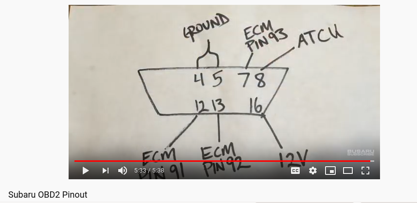